


Figure 1 shows a common slotted waveguide diagram, which has a long and narrow waveguide structure with a slot in the middle. This slot can be used to transmit electromagnetic waves.
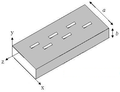
figure 1. Geometry of the most common slotted waveguide antennas.
The front-end (Y = 0 open face in the xz plane) antenna is fed. The far end is usually a short circuit (metallic enclosure). The waveguide may be excited by a short dipole (seen on the back of the cavity slot antenna) on the page, or by another waveguide.
To begin analyzing the Figure 1 antenna, let's look at the circuit model. The waveguide itself acts as a transmission line, and the slots in the waveguide can be viewed as parallel (parallel) admittances. The waveguide is short-circuited, so the approximate circuit model is shown in Figure 1:
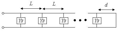
figure 2. Circuit model of slotted waveguide antenna.
The last slot is a distance "d" to the end (which is short-circuited, as shown in Figure 2), and the slot elements are spaced a distance "L" from each other.
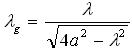
The size of the groove will give a guide to the wavelength. The guide wavelegnth is the wavelength within the waveguide. The guide wavelength ( ) is a function of the width of the waveguide ("a") and the free space wavelength. For the dominant TE01 mode, the guidance wavelengths are:

The distance between the last slot and the end "d" is often chosen to be a quarter wavelength. The theoretical state of the transmission line, the quarter-wavelength short-circuit impedance line transmitted downward is open circuit. Therefore, Figure 2 reduces to:
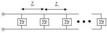
image 3. Slotted waveguide circuit model using quarter-wavelength transformation.
If parameter "L" is selected to be a half wavelength, then the input ž ohmic impedance is viewed at a half wavelength distance z ohms. The "L" is a reason for the design to be about half a wavelength. If the waveguide slot antenna is designed in this way, then all slots can be considered parallel. Therefore, the input admittance and input impedance of an "N" element slotted array can be quickly calculated as:
The input impedance of the waveguide is a function of the slot impedance.
Please note that the above design parameters are only valid at a single frequency. As the frequency proceeds from there the waveguide design works, there will be degradation in the performance of the antenna. As an example of thinking about the frequency characteristics of a slotted waveguide, measurements of a sample as a function of frequency will be shown in S11. The waveguide is designed to operate at 10 GHz. This is fed to the coaxial feed at the bottom, as shown in Figure 4.
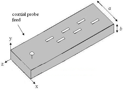
Figure 4. The slotted waveguide antenna is fed by a coaxial feed.
The resulting S-parameter plot is shown below.
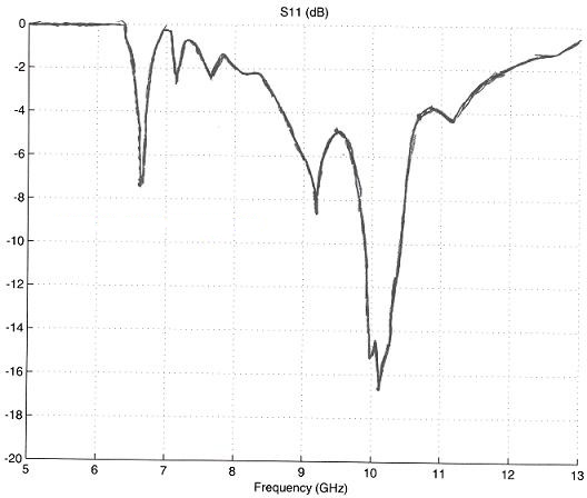
NOTE: The antenna has a very large drop-off on the S11 at about 10 GHz. This shows that most of the power consumption is radiated at this frequency. The antenna bandwidth (if defined as S11 is less than -6 dB) goes from about 9.7 GHz to 10.5 GHz, giving a fractional bandwidth of 8%. Note that there is also a resonance around 6.7 and 9.2 GHz. Below 6.5 GHz, below the cutoff waveguide frequency and almost no energy is radiated. The S-parameter plot shown above gives a good idea of what bandwidth slotted waveguide frequency characteristics are similar to.
The three-dimensional radiation pattern of a slotted waveguide is shown below (this was calculated using a numerical electromagnetic package called FEKO). The gain of this antenna is approximately 17 dB.
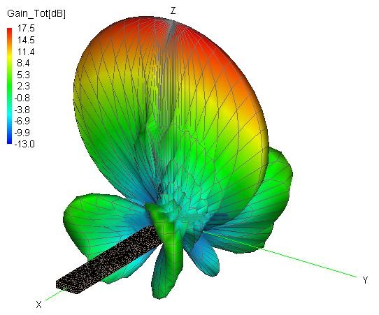
Note that in the X-Z plane (H-plane), the beamwidth is very narrow (2-5 degrees). In the Y-Z plane (or E-plane), the beamwidth is much larger.
Slotted Waveguide Antenna series product introduction:
Post time: Jan-05-2024


