


In order to adapt to the antenna angle requirements of the new product and share the previous generation PCB sheet mold, the following antenna layout can be used to achieve antenna gain of 14dBi@77GHz and radiation performance of 3dB_E/H_Beamwidth=40°. Using Rogers 4830 plate, thickness 0.127mm, Dk=3.25, Df=0.0033.
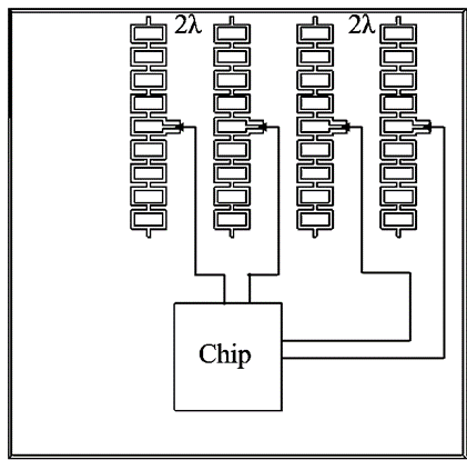
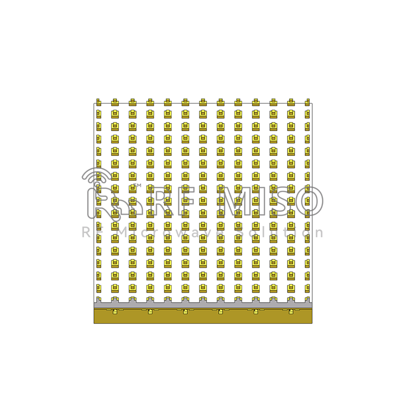
Antenna layout
In the above figure, a microstrip grid antenna is used. The microstrip grid array antenna is an antenna form formed by cascading radiating elements and transmission lines formed by N microstrip rings. It has compact structure, high gain, simple feeding and Ease of manufacture and other advantages. The main polarization method is linear polarization, which is similar to conventional microstrip antennas and can be processed by etching technology. The grid's impedance, feed location, and interconnection structure together determine the current distribution across the array, and the radiation characteristics depend on the grid's geometry. A single grid size is used to determine the center frequency of the antenna.
RFMISO array antenna series products:
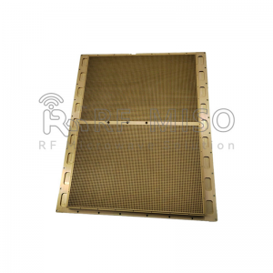
RM-PA7087-43
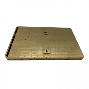
RM-PA1075145-32
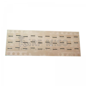
RM-SWA910-22
RM-PA10145-30
Principle analysis
The current flowing in the vertical direction of the array element has equal amplitude and reverse direction, and the radiation capability is weak, which has little impact on the antenna performance. Set the cell width l1 to half wavelength and adjust the cell height (h) to achieve a phase difference of 180° between a0 and b0. For broadside radiation, the phase difference between points a1 and b1 is 0°.
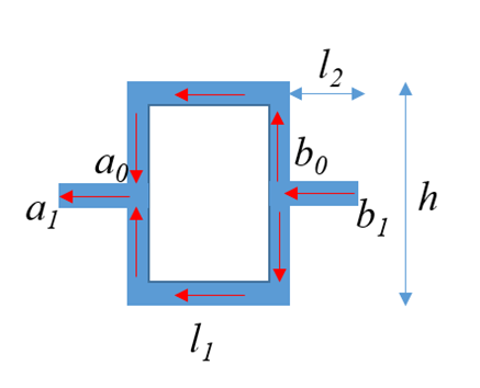
Array element structure
Feed structure
Grid-type antennas usually use a coaxial feed structure, and the feeder is connected to the back of the PCB, so the feeder needs to be designed through layers. For actual processing, there will be a certain accuracy error, which will affect performance. In order to meet the phase information described in the above figure, a planar differential feed structure can be used, with equal amplitude excitation at the two ports, but a phase difference of 180°.
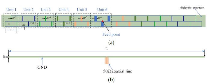
Coaxial feed structure[1]
Most microstrip grid array antennas use coaxial feeding. The feeding positions of the grid array antenna are mainly divided into two types: center feeding (feeding point 1) and edge feeding (feeding point 2 and feeding point 3).

Typical grid array structure
During edge feeding, there are traveling waves spanning the entire grid on the grid array antenna, which is a non-resonant single-direction end-fire array. The grid array antenna can be used as both a traveling wave antenna and a resonant antenna. Selecting the appropriate frequency, feed point, and grid size allows the grid to operate in different states: traveling wave (frequency sweep) and resonance (edge emission). As a traveling wave antenna, the grid array antenna adopts an edge-fed feed form, with the short side of the grid slightly larger than one-third of the guided wavelength and the long side between two and three times the length of the short side. The current on the short side is transmitted to the other side, and there is a phase difference between the short sides. Traveling wave (non-resonant) grid antennas radiate tilted beams that deviate from the normal direction of the grid plane. The beam direction changes with frequency and can be used for frequency scanning. When the grid array antenna is used as a resonant antenna, the long and short sides of the grid are designed to be one conductive wavelength and half a conductive wavelength of the central frequency, and the central feeding method is adopted. The instantaneous current of the grid antenna in the resonant state presents a standing wave distribution. Radiation is mainly generated by the short sides, with the long sides acting as transmission lines. The grid antenna obtains better radiation effect, the maximum radiation is in the wide-side radiation state, and the polarization is parallel to the short side of the grid. When the frequency deviates from the designed center frequency, the short side of the grid is no longer half the guide wavelength, and beam splitting occurs in the radiation pattern. [2]
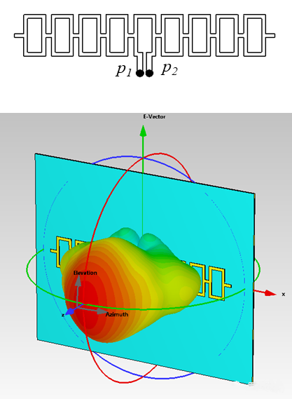
Array model and its 3D pattern
As shown in the above figure of the antenna structure, where P1 and P2 are 180° out of phase, ADS can be used for schematic simulation (not modeled in this article). By differentially feeding the feed port, the current distribution on a single grid element can be observed, as shown in the principle analysis. The currents in the longitudinal position are in opposite directions (cancellation), and the currents in the transverse position are of equal amplitude and in phase (superposition).
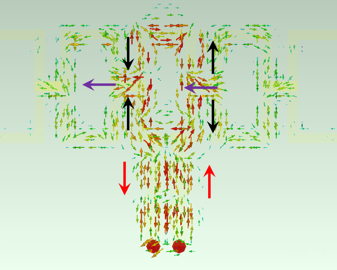
Current distribution on different arms1
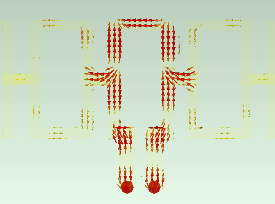
Current distribution on different arms 2
The above gives a brief introduction to the grid antenna, and designs an array using a microstrip feed structure operating at 77GHz. In fact, according to the radar detection requirements, the vertical and horizontal numbers of the grid can be reduced or increased to achieve an antenna design at a specific angle. In addition, the length of the microstrip transmission line can be modified in the differential feed network to achieve the corresponding phase difference.
Post time: Jan-24-2024


