


Horn antenna is one of the widely used antennas with simple structure, wide frequency range, large power capacity and high gain. Horn antennas are often used as feed antennas in large-scale radio astronomy, satellite tracking, and communication antennas. In addition to serving as a feed for reflectors and lenses, it is a common element in phased arrays and serves as a common standard for calibration and gain measurements of other antennas.
A horn antenna is formed by gradually unfolding a rectangular waveguide or a circular waveguide in a specific manner. Due to the gradual expansion of the waveguide mouth surface, the matching between the waveguide and the free space is improved, making the reflection coefficient smaller. For the fed rectangular waveguide, single-mode transmission should be achieved as much as possible, that is, only TE10 waves are transmitted. This not only concentrates the signal energy and reduces the loss, but also avoids the impact of inter-mode interference and additional dispersion caused by multiple modes. .
According to the different deployment methods of horn antennas, they can be divided into sector horn antennas, pyramid horn antennas, conical horn antennas, corrugated horn antennas, ridged horn antennas, multi-mode horn antennas, etc. These common horn antennas are described below. Introduction one by one
Sector horn antenna
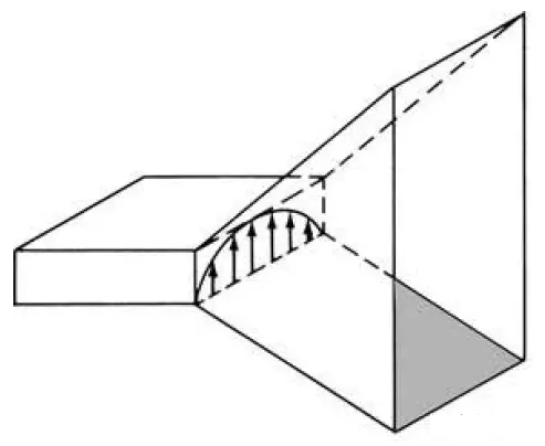
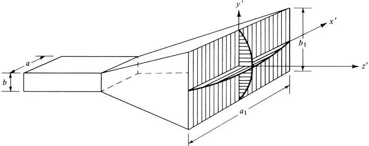
E-plane sector horn antenna
The E-plane sector horn antenna is made of a rectangular waveguide opened at a certain angle in the direction of the electric field.
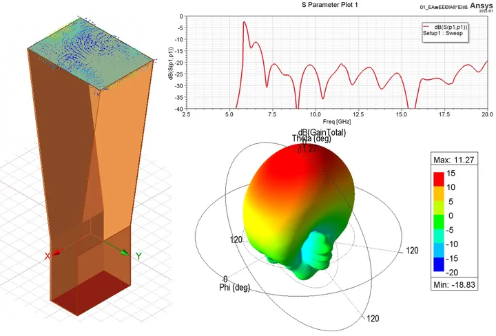
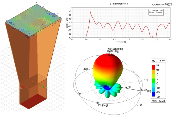
The figure below shows the simulation results of the E-plane sector horn antenna. It can be seen that the beam width of this pattern in the E-plane direction is narrower than in the H-plane direction, which is caused by the larger aperture of the E-plane.
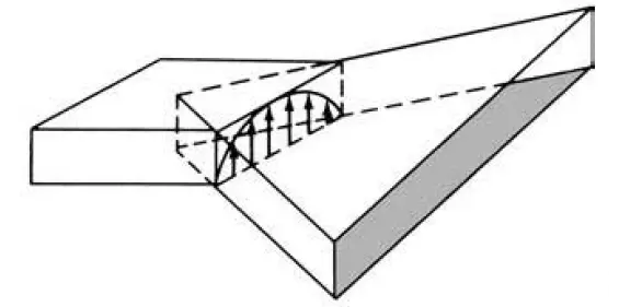
H-plane sector horn antenna
The H-plane sector horn antenna is made of a rectangular waveguide opened at a certain angle in the direction of the magnetic field.
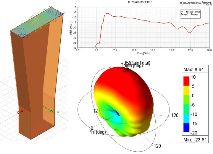
The figure below shows the simulation results of the H-plane sector horn antenna. It can be seen that the beam width of this pattern in the H-plane direction is narrower than in the E-plane direction, which is caused by the larger aperture of the H-plane.
RFMISO sector horn antenna products:

RM-SWHA187-10

RM-SWHA28-10
Pyramid Horn Antenna
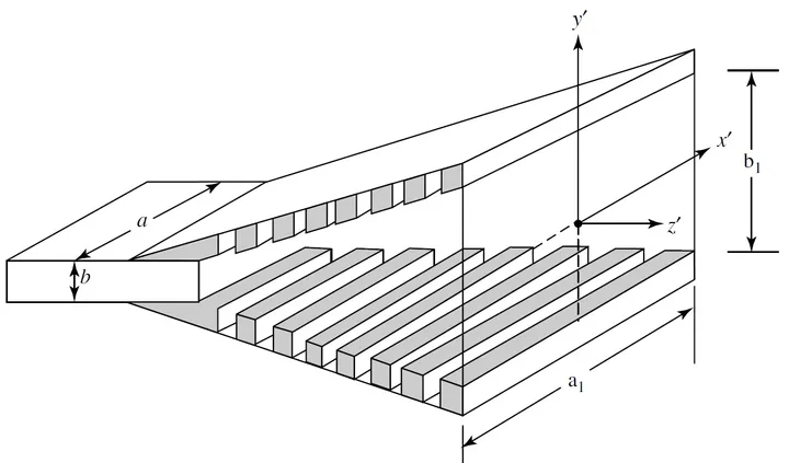
The pyramid horn antenna is made of a rectangular waveguide that is opened at a certain angle in two directions at the same time.
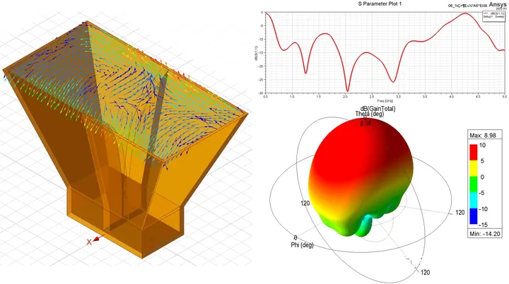
The figure below shows the simulation results of a pyramidal horn antenna. Its radiation characteristics are basically a combination of E-plane and H-plane sector horns.
Conical horn antenna
When the open end of a circular waveguide is horn-shaped, it is called a conical horn antenna. A cone horn antenna has a circular or elliptical aperture above it.
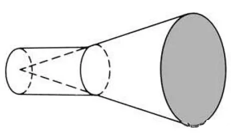
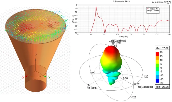
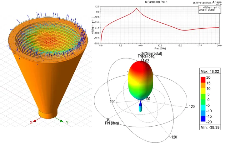
The figure below shows the simulation results of the conical horn antenna.
RFMISO conical horn antenna products:

RM-CDPHA218-15

RM-CDPHA618-17
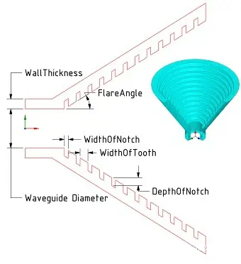
Corrugated horn antenna
A corrugated horn antenna is a horn antenna with a corrugated inner surface. It has the advantages of wide frequency band, low cross-polarization, and good beam symmetry performance, but its structure is complex, and the processing difficulty and cost are high.
Corrugated horn antennas can be divided into two types: pyramidal corrugated horn antennas and conical corrugated horn antennas.
RFMISO corrugated horn antenna products:

RM-CHA140220-22
Pyramidal corrugated horn antenna
Conical corrugated horn antenna
The figure below shows the simulation results of the conical corrugated horn antenna.
Ridged horn antenna
When the operating frequency of conventional horn antenna is greater than 15 GHz, the back lobe begins to split and the side lobe level increases. Adding a ridge structure to the speaker cavity can increase bandwidth, reduce impedance, increase gain, and enhance the directionality of radiation.
Ridged horn antennas are mainly divided into double-ridged horn antennas and four-ridged horn antennas. The following uses the most common pyramidal double-ridged horn antenna as an example for simulation.
Pyramid Double Ridge Horn Antenna
Adding two ridge structures between the waveguide part and the horn opening part is a double-ridge horn antenna. The waveguide section is divided into a back cavity and a ridge waveguide. The back cavity can filter out the higher-order modes excited in the waveguide. The ridge waveguide reduces the cutoff frequency of the main mode transmission, thus achieving the purpose of broadening the frequency band.
The ridged horn antenna is smaller than the general horn antenna in the same frequency band and has a higher gain than the general horn antenna in the same frequency band.
The figure below shows the simulation results of the pyramidal double-ridged horn antenna.
Multimode horn antenna
In many applications, horn antennas are required to provide symmetrical patterns in all planes, phase center coincidence in the $E$ and $H$ planes, and side lobe suppression.
The multi-mode excitation horn structure can improve the beam equalization effect of each plane and reduce the side lobe level. One of the most common multimode horn antennas is the dual-mode conical horn antenna.
Dual Mode Conical Horn Antenna
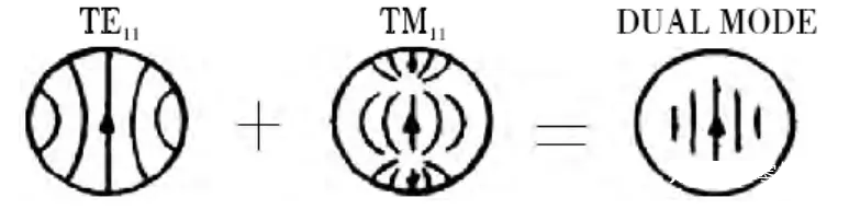
The dual-mode cone horn improves the $E$ plane pattern by introducing a higher-order mode TM11 mode, so that its pattern has axially symmetrical equalized beam characteristics. The figure below is a schematic diagram of the aperture electric field distribution of the main mode TE11 mode and the higher-order mode TM11 in a circular waveguide and its synthesized aperture field distribution.
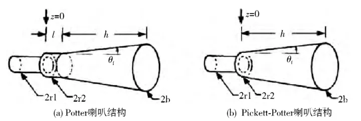
The structural implementation form of the dual-mode conical horn is not unique. Common implementation methods include Potter horn and Pickett-Potter horn.
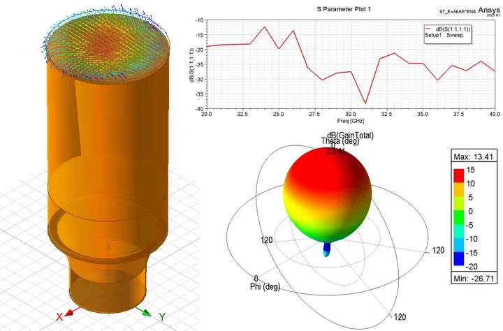
The figure below shows the simulation results of the Potter dual-mode conical horn antenna.
Post time: Mar-01-2024


