


How to achieve impedance matching of waveguides? From the transmission line theory in microstrip antenna theory, we know that appropriate series or parallel transmission lines can be selected to achieve impedance matching between transmission lines or between transmission lines and loads to achieve maximum power transmission and minimum reflection loss. The same principle of impedance matching in microstrip lines applies to impedance matching in waveguides. Reflections in waveguide systems can lead to impedance mismatches. When impedance deterioration occurs, the solution is the same as for transmission lines, that is, changing the required value The lumped impedance is placed at pre-calculated points in the waveguide to overcome the mismatch, thereby eliminating the effects of reflections. While transmission lines use lumped impedances or stubs, waveguides use metal blocks of various shapes.
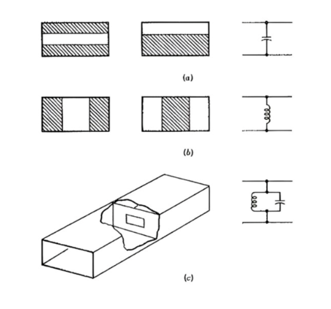
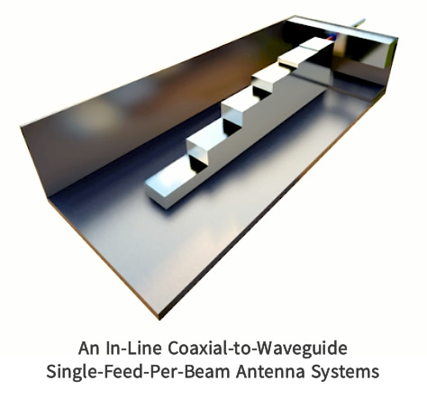
figure 1:Waveguide irises and equivalent circuit,(a)Capacitive;(b)inductive;(c)resonant.
Figure 1 shows the different kinds of impedance matching, taking any of the forms shown and can be capacitive, inductive or resonant. The mathematical analysis is complex, but the physical explanation is not. Considering the first capacitive metal strip in the figure, it can be seen that the potential that existed between the top and bottom walls of the waveguide (in the dominant mode) now exists between the two metal surfaces in closer proximity, so the capacitance is The point increases. In contrast, the metal block in Figure 1b allows current to flow where it did not flow before. There will be current flow in the previously enhanced electric field plane due to the addition of the metal block. Therefore, energy storage occurs in the magnetic field and the inductance at that point of the waveguide increases. In addition, if the shape and position of the metal ring in Figure c are designed reasonably, the inductive reactance and capacitive reactance introduced will be equal, and the aperture will be parallel resonance. This means that the impedance matching and tuning of the main mode is very good, and the shunting effect of this mode will be negligible. However, other modes or frequencies will be attenuated, so the resonant metal ring acts as both a bandpass filter and a mode filter.
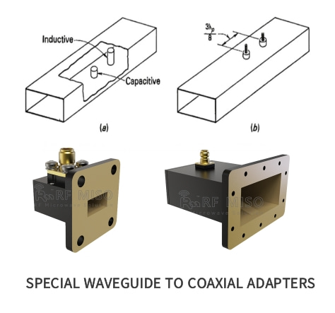
figure 2:(a)waveguide posts;(b)two-screw matcher
Another way to tune is shown above, where a cylindrical metal post extends from one of the wide sides into the waveguide, having the same effect as a metal strip in terms of providing lumped reactance at that point. The metal post can be capacitive or inductive, depending on how far it extends into the waveguide. Essentially, this matching method is that when such a metal pillar extends slightly into the waveguide, it provides a capacitive susceptance at that point, and the capacitive susceptance increases until the penetration is about a quarter of a wavelength, At this point, series resonance occurs. Further penetration of the metal post results in an inductive susceptance being provided which decreases as insertion becomes more complete. The resonance intensity at the midpoint installation is inversely proportional to the diameter of the column and can be used as a filter, however, in this case it is used as a band stop filter to transmit higher order modes. Compared with increasing the impedance of metal strips, a major advantage of using metal posts is that they are easy to adjust. For example, two screws can be used as tuning devices to achieve efficient waveguide matching.
Resistive loads and attenuators:
Like any other transmission system, waveguides sometimes require perfect impedance matching and tuned loads to fully absorb incoming waves without reflection and to be frequency insensitive. One application for such terminals is to make various power measurements on the system without actually radiating any power.
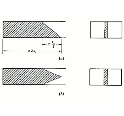
figure 3 waveguide resistance load(a)single taper(b)double taper
The most common resistive termination is a section of lossy dielectric installed at the end of the waveguide and tapered (with the tip pointed toward the incoming wave) so as not to cause reflections. This lossy medium may occupy the entire width of the waveguide, or it may occupy only the center of the end of the waveguide, as shown in Figure 3. The taper can be single or double taper and typically has a length of λp/2, with a total length of approximately two wavelengths. Usually made of dielectric plates such as glass, coated with carbon film or water glass on the outside. For high-power applications, such terminals can have heat sinks added to the outside of the waveguide, and the power delivered to the terminal can be dissipated through the heat sink or through forced air cooling.
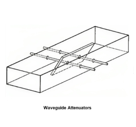
figure 4 Movable vane attenuator
Dielectric attenuators can be made removable as shown in Figure 4. Placed in the middle of the waveguide, it can be moved laterally from the center of the waveguide, where it will provide the greatest attenuation, to the edges, where the attenuation is greatly reduced since the electric field strength of the dominant mode is much lower.
Attenuation in waveguide:
The energy attenuation of waveguides mainly includes the following aspects:
1. Reflections from internal waveguide discontinuities or misaligned waveguide sections
2. Losses caused by current flowing in waveguide walls
3. Dielectric losses in filled waveguides
The last two are similar to the corresponding losses in coaxial lines and are both relatively small. This loss depends on the wall material and its roughness, the dielectric used and the frequency (due to the skin effect). For brass conduit, the range is from 4 dB/100m at 5 GHz to 12 dB/100m at 10 GHz, but for aluminum conduit, the range is lower. For silver-coated waveguides, losses are typically 8dB/100m at 35 GHz, 30dB/100m at 70 GHz, and close to 500 dB/100m at 200 GHz. To reduce losses, especially at the highest frequencies, waveguides are sometimes plated (internally) with gold or platinum.
As already pointed out, the waveguide acts as a high-pass filter. Although the waveguide itself is virtually lossless, frequencies below the cutoff frequency are severely attenuated. This attenuation is due to reflection at the waveguide mouth rather than propagation.
Waveguide coupling:
Waveguide coupling usually occurs through flanges when waveguide pieces or components are joined together. The function of this flange is to ensure a smooth mechanical connection and suitable electrical properties, in particular low external radiation and low internal reflection.
Flange:
Waveguide flanges are widely used in microwave communications, radar systems, satellite communications, antenna systems, and laboratory equipment in scientific research. They are used to connect different waveguide sections, ensure leakage and interference are prevented, and maintain precise alignment of the waveguide to ensure high Reliable transmission and precise positioning of frequency electromagnetic waves. A typical waveguide has a flange at each end, as shown in Figure 5.
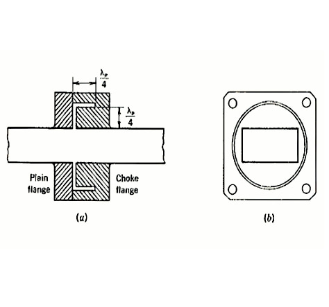
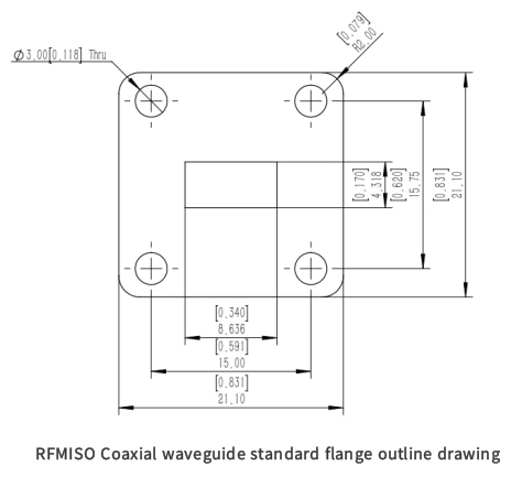
figure 5 (a)plain flange;(b)flange coupling.
At lower frequencies the flange will be brazed or welded to the waveguide, while at higher frequencies a flatter butt flat flange is used. When two parts are joined, the flanges are bolted together, but the ends must be finished smoothly to avoid discontinuities in the connection. It's obviously easier to align the components correctly with some adjustments, so smaller waveguides are sometimes equipped with threaded flanges that can be screwed together with a ring nut. As frequency increases, the size of the waveguide coupling naturally decreases, and the coupling discontinuity becomes larger in proportion to the signal wavelength and waveguide size. Therefore, discontinuities at higher frequencies become more troublesome.
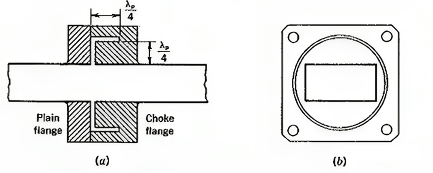
figure 6 (a)Cross section of choke coupling;(b)end view of choke flange
To solve this problem, a small gap can be left between the waveguides, as shown in Figure 6. A choke coupling consisting of an ordinary flange and a choke flange connected together. To compensate for possible discontinuities, a circular choke ring with an L-shaped cross-section is used in the choke flange to achieve a tighter fitting connection. Unlike ordinary flanges, choke flanges are frequency sensitive, but an optimized design can ensure a reasonable bandwidth (perhaps 10% of the center frequency) over which the SWR does not exceed 1.05.
Post time: Jan-15-2024


