


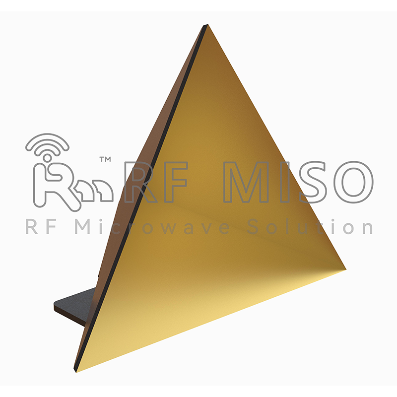
A trihedral reflector, also known as a corner reflector or triangular reflector, is a passively target device commonly used in antennas and radar systems. It consists of three planar reflectors forming a closed triangular structure. When an electromagnetic wave hits a trihedral reflector, it will be reflected back along the incident direction, forming a reflected wave that is equal in direction but opposite in phase to the incident wave.
The following is a detailed introduction to trihedral corner reflectors:
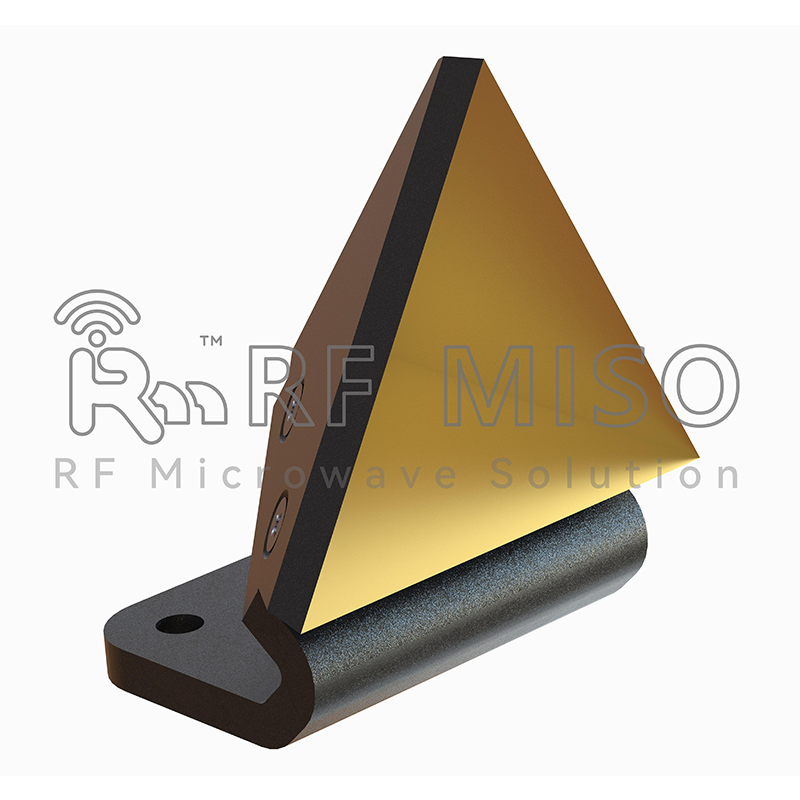
Structure and principle:
A trihedral corner reflector consists of three planar reflectors centered on a common intersection point, forming an equilateral triangle. Each plane reflector is a plane mirror that can reflect incident waves according to the law of reflection. When an incident wave hits the trihedral corner reflector, it will be reflected by each planar reflector and eventually form a reflected wave. Due to the geometry of the trihedral reflector, the reflected wave is reflected in an equal but opposite direction than the incident wave.
Features and Applications:
1. Reflection characteristics: Trihedral corner reflectors have high reflection characteristics at a certain frequency. It can reflect the incident wave back with high reflectivity, forming an obvious reflection signal. Due to the symmetry of its structure, the direction of the reflected wave from the trihedral reflector is equal to the direction of the incident wave but opposite in phase.
2. Strong reflected signal: Since the phase of the reflected wave is opposite, when the trihedral reflector is opposite to the direction of the incident wave, the reflected signal will be very strong. This makes the trihedral corner reflector an important application in radar systems to enhance the echo signal of the target.
3. Directivity: The reflection characteristics of the trihedral corner reflector are directional, that is, a strong reflection signal will only be generated at a specific incident angle. This makes it very useful in directional antennas and radar systems for locating and measuring target positions.
4. Simple and economical: The structure of the trihedral corner reflector is relatively simple and easy to manufacture and install. It is usually made of metallic materials, such as aluminum or copper, which has a lower cost.
5. Application fields: Trihedral corner reflectors are widely used in radar systems, wireless communications, aviation navigation, measurement and positioning and other fields. It can be used as target identification, ranging, direction finding and calibration antenna, etc.
Below we will introduce this product in detail:
To increase the directivity of an antenna, a fairly intuitive solution is to use a reflector. For example, if we start with a wire antenna (lets say a half-wave dipole antenna), we could place a conductive sheet behind it to direct radiation in the forward direction. To further increase the directivity, a corner reflector may be used, as shown in Figure 1. The angle between the plates will be 90 degrees.
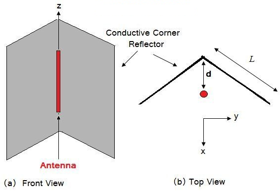
Figure 1. Geometry of Corner Reflector.
The radiation pattern of this antenna can be understood by using image theory, and then calculating the result via array theory. For ease of analysis, we'll assume the reflecting plates are infinite in extent. Figure 2 below shows the equivalent source distribution, valid for the region in front of the plates.
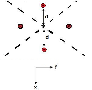
Figure 2. Equivalent sources in free space.
The dotted circles indicate antennas that are in-phase with the actual antenna; the x'd out antennas are 180 degrees out of phase to the actual antenna.
Assume that the original antenna has an omnidirectional pattern given by ( ). Then the radiation pattern (R) of the "equivalent set of radiators" of Figure 2 can be written as:


The above directly follows from Figure 2 and array theory (k is the wave number. The resulting pattern will have the same polarization as the original vertically polarized antenna. The directivity will be increased by 9-12 dB. The above equation gives the radiated fields in the region in front of the plates. Since we assumed the plates were infinite, the fields behind the plates are zero.
The directivity will be the highest when d is a half-wavelength. Assuming the radiating element of Figure 1 is a short dipole with a pattern given by ( ),the fields for this case are shown in Figure 3.

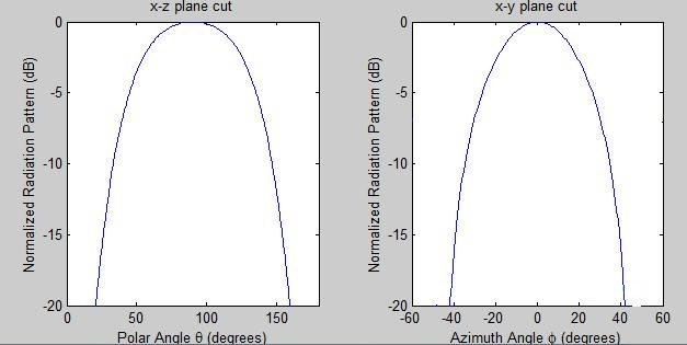
Figure 3. Polar and azimuth patterns of normalized radiation pattern.
The radiation pattern, impedance and gain of the antenna will be influenced by the distance d of Figure 1. The input impedance is increased by the reflector when the spacing is one half wavelength; it can be reduced by moving the antenna closer to the reflector. The length L of the reflectors in Figure 1 are typically 2*d. However, if tracing a ray travelling along the y-axis from the antenna, this will be reflected if the length is at least ( ). The height of the plates should be taller than the radiating element; however since linear antennas do not radiate well along the z-axis, this parameter is not critically important.
Trihedral Corner Reflector series product introduction:

RM-TCR406.4
RM-TCR342.9
RM-TCR330
RM-TCR61
RM-TCR45.7
RM-TCR35.6
Post time: Jan-12-2024


