


Polarization is one of the basic characteristics of antennas. We first need to understand the polarization of plane waves. We can then discuss the main types of antenna polarization.
linear polarization
We will begin to understand the polarization of a plane electromagnetic wave.
A planar electromagnetic (EM) wave has several characteristics. The first is that the power travels in one direction (no field changes in two orthogonal directions). Second, the electric field and the magnetic field are perpendicular to each other and orthogonal to each other. Electric and magnetic fields are perpendicular to the direction of plane wave propagation. As an example, consider a single-frequency electric field (E field) given by equation (1). The electromagnetic field is traveling in the +z direction. The electric field is directed in the +x direction. The magnetic field is in the +y direction.
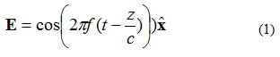
In equation (1), observe the notation: . This is a unit vector (a vector of length), which says that the electric field point is in the x direction. The plane wave is illustrated in Figure 1.

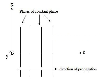
figure 1. Graphical representation of the electric field traveling in the +z direction.
Polarization is the trace and propagation shape (contour) of an electric field. As an example, consider the plane wave electric field equation (1). We will observe the position where the electric field is (X,Y,Z) = (0,0,0) as a function of time. The amplitude of this field is plotted in Figure 2, at several instances in time. The field is oscillating at frequency "F".
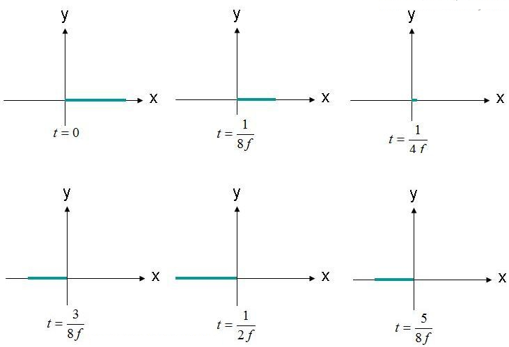
figure 2. Observe the electric field (X, Y, Z) = (0,0,0) at different times.
The electric field is observed at the origin, oscillating back and forth in amplitude. The electric field is always along the indicated x-axis. Since the electric field is maintained along a single line, this field can be said to be linearly polarized. Additionally, if the X-axis is parallel to the ground, this field is also described as horizontally polarized. If the field is oriented along the Y-axis, the wave can be said to be vertically polarized.
Linearly polarized waves do not need to be directed along a horizontal or vertical axis. For example, an electric field wave with a constraint lying along a line as shown in Figure 3 would also be linearly polarized.
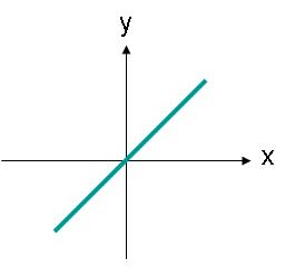
image 3. The electric field amplitude of a linearly polarized wave whose trajectory is an angle.
The electric field in Figure 3 can be described by equation (2). Now there is an x and y component of the electric field. Both components are equal in size.
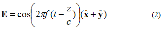
One thing to note about equation (2) is the x-y-component and electronic fields in the second stage. This means that both components have the same amplitude at all times.
circular polarization
Now assume that the electric field of a plane wave is given by equation (3):
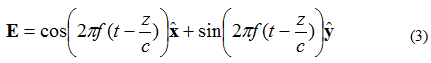
In this case, the X- and Y-elements are 90 degrees out of phase. If the field is observed as (X, Y, Z) = (0,0,0) again as before, the electric field versus time curve will appear as shown below in Figure 4.
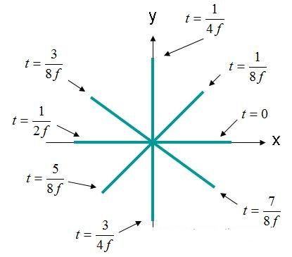
Figure 4. Electric field strength (X, Y, Z) = (0,0,0) EQ domain. (3).
The electric field in Figure 4 rotates in a circle. This type of field is described as a circularly polarized wave. For circular polarization, the following criteria must be met:
- Standard for circular polarization
- The electric field must have two orthogonal (perpendicular) components.
- The orthogonal components of the electric field must have equal amplitudes.
- The quadrature components must be 90 degrees out of phase.
If traveling on the Wave Figure 4 screen, the field rotation is said to be counterclockwise and right-handed circularly polarized (RHCP). If the field is rotated in a clockwise direction, the field will be left-handed circular polarization (LHCP).
Elliptical polarization
If the electric field has two perpendicular components, 90 degrees out of phase but of equal magnitude, the field will be elliptically polarized. Considering the electric field of a plane wave traveling in the +z direction, described by Equation (4):
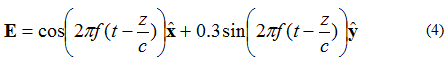
The locus of the point at which the tip of the electric field vector will assume is given in Figure 5
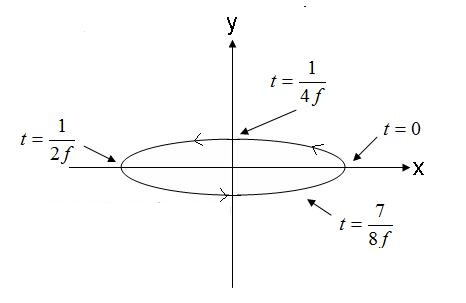
Figure 5. Prompt elliptical polarization wave electric field. (4).
The field in Figure 5, traveling in a counterclockwise direction, would be right-handed elliptical if traveling out of the screen. If the electric field vector rotates in the opposite direction, the field will be left-handed elliptically polarized.
Furthermore, elliptical polarization refers to its eccentricity. The ratio of eccentricity to the amplitude of the major and minor axes. For example, the wave eccentricity from equation (4) is 1/0.3= 3.33. Elliptically polarized waves are further described by the direction of the major axis. The wave equation (4) has an axis primarily consisting of the x-axis. Note that the major axis can be at any plane angle. The angle is not required to fit the X, Y or Z axis. Finally, it is important to note that both circular and linear polarization are special cases of elliptical polarization. 1.0 eccentric elliptically polarized wave is a circularly polarized wave. Elliptically polarized waves with infinite eccentricity. Linearly polarized waves.
Antenna polarization
Now that we are aware of polarized plane wave electromagnetic fields, the polarization of an antenna is simply defined.
Antenna Polarization An antenna far-field evaluation, the polarization of the resulting radiated field. Therefore, antennas are often listed as "linearly polarized" or "right-handed circularly polarized antennas".
This simple concept is important for antenna communications. First, a horizontally polarized antenna will not communicate with a vertically polarized antenna. Due to the reciprocity theorem, the antenna transmits and receives in exactly the same way. Therefore, vertically polarized antennas transmit and receive vertically polarized fields. Therefore, if you try to convey a vertically polarized horizontally polarized antenna, there will be no reception.
In the general case, for two linearly polarized antennas rotated relative to each other by an angle ( ), the power loss due to this polarization mismatch will be described by the polarization loss factor (PLF):

Therefore, if two antennas have the same polarization, the angle between their radiating electron fields is zero and there is no power loss due to polarization mismatch. If one antenna is vertically polarized and the other is horizontally polarized, the angle is 90 degrees, and no power will be transferred.
NOTE: Moving the phone over your head to different angles explains why reception can sometimes be increased. Cell phone antennas are usually linearly polarized, so rotating the phone can often match the polarization of the phone, thus improving reception.
Circular polarization is a desirable characteristic of many antennas. Both antennas are circularly polarized and do not suffer from signal loss due to polarization mismatch. Antennas used in GPS systems are right-hand circularly polarized.
Now assume that a linearly polarized antenna receives circularly polarized waves. Equivalently, assume that a circularly polarized antenna attempts to receive linearly polarized waves. What is the resulting polarization loss factor?
Recall that circular polarization is actually two orthogonal linearly polarized waves, 90 degrees out of phase. Therefore, a linearly polarized (LP) antenna will only receive the circularly polarized (CP) wave phase component. Therefore, the LP antenna will have a polarization mismatch loss of 0.5 (-3dB). This is true no matter what angle the LP antenna is rotated. therefore:
Polarization loss factor is sometimes referred to as polarization efficiency, antenna mismatch factor, or antenna reception factor. All these names refer to the same concept.
Post time: Dec-22-2023


