


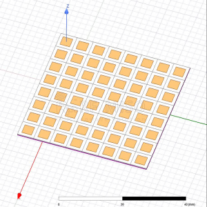
The structure of a microstrip antenna generally consists of a dielectric substrate, a radiator and a ground plate. The thickness of the dielectric substrate is much smaller than the wavelength. The thin metal layer on the bottom of the substrate is connected to the ground plate. On the front side, a thin metal layer with a specific shape is made through a photolithography process as a radiator. The shape of the radiating plate can be changed in many ways according to requirements.
The rise of microwave integration technology and new manufacturing processes has promoted the development of microstrip antennas. Compared with traditional antennas, microstrip antennas are not only small in size, light in weight, low in profile, easy to conform, easy to integrate, low in cost, and suitable for mass production, but also have the advantages of diversified electrical properties.
The four basic feeding methods of microstrip antennas are as follows:
1. (Microstrip Feed): This is one of the most common feeding methods for microstrip antennas. The RF signal is transmitted to the radiating part of the antenna through the microstrip line, usually through coupling between the microstrip line and the radiating patch. This method is simple and flexible and suitable for the design of many microstrip antennas.
2. (Aperture-coupled Feed): This method uses the slots or holes on the microstrip antenna base plate to feed the microstrip line into the radiating element of the antenna. This method can provide better impedance matching and radiation efficiency, and can also reduce the horizontal and vertical beam width of side lobes.
3. (Proximity Coupled Feed): This method uses an oscillator or inductive element near the microstrip line to feed the signal into the antenna. It can provide higher impedance matching and wider frequency band, and is suitable for the design of wide-band antennas.
4. (Coaxial Feed): This method uses coplanar wires or coaxial cables to feed RF signals into the radiating part of the antenna. This method usually provides good impedance matching and radiation efficiency, and is especially suitable for situations where a single antenna interface is required.
Different feeding methods will affect the impedance matching, frequency characteristics, radiation efficiency and physical layout of the antenna.
How to select the coaxial feed point of microstrip antenna
When designing a microstrip antenna, choosing the location of the coaxial feed point is critical to ensuring the performance of the antenna. Here are some suggested methods for selecting coaxial feed points for microstrip antennas:
1. Symmetry: Try to choose the coaxial feed point at the center of the microstrip antenna to maintain the symmetry of the antenna. This helps improve the antenna's radiation efficiency and impedance matching.
2. Where the electric field is the largest: The coaxial feed point is best chosen at the position where the electric field of the microstrip antenna is the largest, which can improve the efficiency of the feed and reduce losses.
3. Where the current is maximum: The coaxial feed point can be selected near the position where the current of the microstrip antenna is maximum to obtain higher radiation power and efficiency.
4. Zero electric field point in single mode: In microstrip antenna design, if you want to achieve single mode radiation, the coaxial feed point is usually selected at the zero electric field point in single mode to achieve better impedance matching and radiation. characteristic.
5. Frequency and waveform analysis: Use simulation tools to perform frequency sweep and electric field/current distribution analysis to determine the optimal coaxial feed point location.
6. Consider the beam direction: If radiation characteristics with specific directivity are required, the location of the coaxial feed point can be selected according to the beam direction to obtain the desired antenna radiation performance.
In the actual design process, it is usually necessary to combine the above methods and determine the optimal coaxial feed point position through simulation analysis and actual measurement results to achieve the design requirements and performance indicators of the microstrip antenna. At the same time, different types of microstrip antennas (such as patch antennas, helical antennas, etc.) may have some specific considerations when selecting the location of the coaxial feed point, which require specific analysis and optimization based on the specific antenna type and application scenario. .
The difference between microstrip antenna and patch antenna
Microstrip antenna and patch antenna are two common small antennas. They have some differences and characteristics:
1. Structure and layout:
- A microstrip antenna usually consists of a microstrip patch and a ground plate. The microstrip patch serves as a radiating element and is connected to the ground plate through a microstrip line.
- Patch antennas are generally conductor patches that are directly etched on a dielectric substrate and do not require microstrip lines like microstrip antennas.
2. Size and shape:
- Microstrip antennas are relatively small in size, often used in microwave frequency bands, and have a more flexible design.
- Patch antennas can also be designed to be miniaturized, and in some specific cases, their dimensions may be smaller.
3. Frequency range:
- The frequency range of microstrip antennas can range from hundreds of megahertz to several gigahertz, with certain broadband characteristics.
- Patch antennas usually have better performance in specific frequency bands and are generally used in specific frequency applications.
4. Production process:
- Microstrip antennas are usually made using printed circuit board technology, which can be mass-produced and have low cost.
- Patch antennas are usually made of silicon-based materials or other special materials, have certain processing requirements, and are suitable for small batch production.
5. Polarization characteristics:
- Microstrip antennas can be designed for linear polarization or circular polarization, giving them a certain degree of flexibility.
- The polarization characteristics of patch antennas usually depend on the structure and layout of the antenna and are not as flexible as microstrip antennas.
In general, microstrip antennas and patch antennas are different in structure, frequency range, and manufacturing process. Choosing the appropriate antenna type needs to be based on specific application requirements and design considerations.
Microstrip antenna product recommendations:
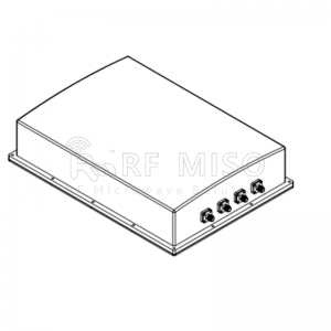
RM-MPA1725-9(1.7-2.5GHz)
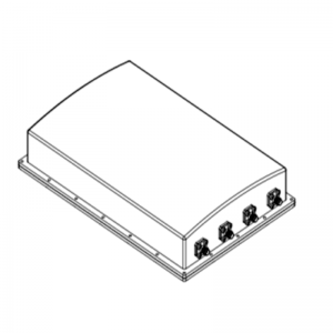
RM-MPA2225-9(2.2-2.5GHz)
RM-MA25527-22(25.5-27GHz)
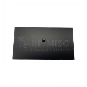
RM-MA424435-22(4.25-4.35GHz)
Post time: Apr-19-2024


