


Fading in wireless communication is the variation of received signal amplitude, phase or power caused by changes in the propagation path. It can reduce link margin, distort wideband signals and make RF measurements difficult to reproduce. Understanding the type of fading present in a system helps engineers choose appropriate antennas, test methods and mitigation techniques.
This guide explains large-scale and small-scale fading, flat and frequency-selective channels, slow and fast fading, and the most common statistical channel models. It also shows how antenna pattern, polarization and test geometry influence practical fading measurements.
What Is Wireless Channel Fading?
A radio signal rarely reaches a receiver through only one ideal path. Buildings, terrain, vehicles, equipment and other objects can block, reflect, diffract or scatter electromagnetic waves. Multiple copies of the same signal may therefore arrive with different delays, amplitudes, phases and angles of arrival. Their combination can be constructive at one location or frequency and destructive at another.
Fading is different from deterministic free-space path loss. Path loss describes the general reduction in power as distance and frequency increase, while fading describes additional variation around that average. Engineers usually classify fading on two independent axes: spatial scale and channel selectivity.
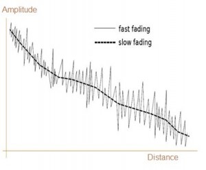
Figure 1. Slow and rapid variations in received signal level illustrate different fading time or distance scales.
How Wireless Fading Is Classified
Large-scale fading describes gradual changes over relatively long distances, mainly from path-loss variation and shadowing. Small-scale fading describes rapid changes over short distances or short time intervals due to multipath and motion.
Small-scale fading can then be classified by delay spread as flat or frequency selective, and by Doppler spread as slow or fast. These are separate classifications: a channel can be flat and fast, flat and slow, frequency selective and fast, or frequency selective and slow.
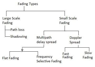
Large-Scale Fading: Path Loss and Shadowing
Path-loss trend
Path loss is the average reduction in received power with propagation distance. In unobstructed free space, the loss is related to wavelength and distance. Real environments add terrain, clutter, atmospheric effects and antenna-height dependencies, so practical link budgets normally use a propagation model appropriate to the deployment scenario.
Shadow fading
Shadowing occurs when large objects partially or completely obstruct the direct propagation path. Buildings, hills, machinery and vehicle bodies can produce relatively slow changes in received level as the transmitter, receiver or surrounding environment changes. Shadow fading is often represented statistically around the local mean path loss.
Small-Scale Fading: Multipath and Motion
Flat fading vs. frequency-selective fading
A channel is approximately flat fading when its coherence bandwidth is wider than the occupied signal bandwidth. The channel then changes the signal amplitude and phase without strongly reshaping its spectrum.
A channel becomes frequency selective when the signal bandwidth is large compared with the coherence bandwidth. Different spectral components experience different gain and phase. The underlying cause is resolvable multipath delay spread, which can create intersymbol interference in digital links.
Slow fading vs. fast fading
Slow fading means the channel changes little during the relevant signaling interval. Fast fading means the channel changes significantly over that interval. Relative motion between the transmitter, receiver and surrounding scatterers produces Doppler shifts and shortens channel coherence time.
| Classification | Key comparison | Typical effect |
|---|---|---|
| Flat fading | Signal bandwidth is smaller than coherence bandwidth | Broad amplitude and phase variation across the whole signal |
| Frequency selective | Signal bandwidth is larger than coherence bandwidth | Spectral distortion and possible intersymbol interference |
| Slow fading | Coherence time is long relative to the signaling interval | Gradual link-level variation |
| Fast fading | Coherence time is short relative to the signaling interval | Rapid variation and Doppler-related impairment |
Common Statistical Fading Models
- Rayleigh fading: commonly used when no single dominant line-of-sight component is present and the received signal is formed by many scattered components.
- Rician fading: includes a dominant component together with scattered multipath components. The Rician K-factor expresses the power ratio between the dominant and diffuse components.
- Nakagami fading: a flexible empirical distribution that can represent a range of fading severities through its shape parameter.
- Weibull fading: another adaptable statistical distribution used for selected measured propagation environments.
Model selection must be based on the actual environment, frequency, mobility, antenna configuration and measurement data. Modern MATLAB workflows use objects such as comm.RayleighChannel and comm.RicianChannel rather than the obsolete functions referenced in the former version of this article.
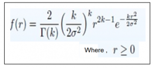
Figure 3. Statistical envelope distributions provide compact models for measured fading behavior.
How Fading Affects RF System Performance
Fading can reduce received power, lower signal-to-noise ratio, increase error rate and interrupt a radio link. Frequency-selective fading can also distort wideband waveforms, while rapid Doppler variation can make channel estimation more difficult.
Common mitigation methods include:
- adequate link margin and automatic gain control;
- time, frequency, spatial or polarization diversity;
- equalization and multicarrier waveform design;
- channel coding, interleaving and adaptive modulation;
- MIMO processing and beam steering;
- careful antenna placement, pattern selection and polarization control.
No single technique eliminates every fading mechanism. The correct approach depends on channel statistics, occupied bandwidth, mobility, coverage requirements and acceptable outage probability.
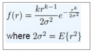
Figure 4. Measured data should determine whether a statistical distribution is appropriate for a specific channel.
Antenna Selection for Channel Sounding and Fading Tests
An antenna does not create the propagation channel by itself, but it strongly affects which paths and polarizations are transmitted or received. Gain, beamwidth, radiation pattern, polarization purity, phase stability and mounting geometry can all influence measured channel behavior.
For repeatable channel or fading measurements, document:
- the complete frequency range and instantaneous measurement bandwidth;
- antenna gain and beamwidth over frequency;
- linear, dual-linear or circular polarization requirements;
- antenna height, orientation, spacing and surrounding structures;
- RF connector, cable loss and calibration reference plane;
- transmitter, receiver and scatterer motion;
- delay spread, Doppler spread and required dynamic range.
RF MISO antenna options
RF MISO designs and supplies RF and microwave antennas for laboratory, field and system-integration work. Depending on the required coverage and measurement geometry, engineers may consider broadband horn antennas for directional wideband measurements, log-periodic antennas for broad frequency coverage, or omnidirectional antennas for selected coverage and propagation studies.
Review the current model datasheet for frequency range, gain, polarization, VSWR, connector and mechanical dimensions. For application-specific selection, share the test band, bandwidth, required pattern, polarization, mounting constraints and measurement environment with the RF MISO team.
Frequently Asked Questions About Wireless Fading
What is fading in wireless communication?
Fading in wireless communication is the variation of received signal amplitude, phase or power caused by multipath propagation, shadowing, movement or changes in the radio environment.
What are the main types of fading?
Fading is commonly classified as large-scale or small-scale. Small-scale fading can also be flat or frequency selective, and slow or fast, depending on delay spread and Doppler spread.
What causes fading in wireless channels?
Common causes include obstruction, reflection, diffraction, scattering, multipath delay and Doppler shifts created by movement of the transmitter, receiver or surrounding objects.
How does antenna selection affect fading measurements?
Antenna gain, beamwidth, polarization, mounting and test geometry influence which propagation paths are transmitted or received, so these factors should be controlled and documented.
Discuss Your RF Measurement Requirement
RF MISO can help identify antenna options for channel sounding, propagation studies, wireless-system evaluation and related RF measurements.
References and Further Reading
Post time: Aug-14-2023


