


A useful parameter calculating the receive power of an antenna is the effective area or effective aperture. Assume that a plane wave with the same polarization as the receive antenna is incident upon the antenna. Further assume that the wave is travelling towards the antenna in the antenna's direction of maximum radiation (the direction from which the most power would be received).
Then the effective aperture parameter describes how much power is captured from a given plane wave. Let p be the power density of the plane wave (in W/m^2). If P_t represents the power (in Watts) at the antennas terminals available to the antenna's receiver, then:
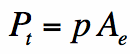
Hence, the effective area simply represents how much power is captured from the plane wave and delivered by the antenna. This area factors in the losses intrinsic to the antenna (ohmic losses, dielectric losses, etc.).
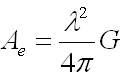
A general relation for the effective aperture in terms of the peak antenna gain (G) of any antenna is given by:

Effective aperture or effective area can be measured on actual antennas by comparison with a known antenna with a given effective aperture, or by calculation using the measured gain and the above equation.
Effective aperture will be a useful concept for calculating received power from a plane wave. To see this in action, go to the next section on the Friis transmission formula.
The Friis Transmission Equation
On this page, we introduce one of the most fundamental equations in antenna theory, the Friis Transmission Equation. The Friis Transmission Equation is used to calculate the power received from one antenna (with gain G1), when transmitted from another antenna (with gain G2), separated by a distance R, and operating at frequency f or wavelength lambda. This page is worth reading a couple times and should be fully understood.
Derivation of Friis Transmission Formula
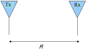
To begin the derivation of the Friis Equation, consider two antennas in free space (no obstructions nearby) separated by a distance R:
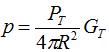
Assume that ( )Watts of total power are delivered to the transmit antenna. For the moment, assume that the transmit antenna is omnidirectional, lossless, and that the receive antenna is in the far field of the transmit antenna. Then the power density p (in Watts per square meter) of the plane wave incident on the receive antenna a distance R from the transmit antenna is given by:

Figure 1. Transmit (Tx) and Receive (Rx) Antennas separated by R.

If the transmit antenna has an antenna gain in the direction of the receive antenna given by( ) , then the power density equation above becomes:

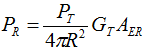
The gain term factors in the directionality and losses of a real antenna. Assume now that the receive antenna has an effective aperture given by( ) . Then the power received by this antenna ( ) is given by:


Since the effective aperture for any antenna can also be expressed as:
The resulting received power can be written as:
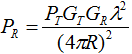
Equation1
This is known as the Friis Transmission Formula. It relates the free space path loss, antenna gains and wavelength to the received and transmit powers. This is one of the fundamental equations in antenna theory, and should be remembered (as well as the derivation above).
Another useful form of the Friis Transmission Equation is given in Equation [2]. Since wavelength and frequency f are related by the speed of light c (see intro to frequency page), we have the Friis Transmission Formula in terms of frequency:
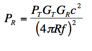
Equation2
Equation [2] shows that more power is lost at higher frequencies. This is a fundamental result of the Friis Transmission Equation. This means that for antennas with specified gains, the energy transfer will be highest at lower frequencies. The difference between the power received and the power transmitted is known as path loss. Said in a different way, Friis Transmission Equation says that the path loss is higher for higher frequencies. The importance of this result from the Friis Transmission Formula cannot be overstated. This is why mobile phones generally operate at less than 2 GHz. There may be more frequency spectrum available at higher frequencies, but the associated path loss will not enable quality reception. As a further consequence of Friss Transmission Equation, suppose you are asked about 60 GHz antennas. Noting that this frequency is very high, you might state that the path loss will be too high for long range communication - and you are absolutely correct. At very high frequencies (60 GHz is sometimes referred to as the mm (millimeter wave) region), the path loss is very high, so only point-to-point communication is possible. This occurs when the receiver and transmitter are in the same room, and facing each other. As a further corrollary of Friis Transmission Formula, do you think the mobile phone operators are happy about the new LTE (4G) band, that operates at 700MHz? The answer is yes: this is a lower frequency than antennas traditionally operate at, but from Equation [2], we note that the path loss will therefore be lower as well. Hence, they can "cover more ground" with this frequency spectrum, and a Verizon Wireless executive recently called this "high quality spectrum", precisely for this reason. Side Note: On the other hand, the cell phone makers will have to fit an antenna with a larger wavelength in a compact device (lower frequency = larger wavelength), so the antenna designer's job got a little more complicated!
Finally, if the antennas are not polarization matched, the above received power could be multiplied by the Polarization Loss Factor (PLF) to properly account for this mismatch. Equation [2] above can be altered to produce a generalized Friis Transmission Formula, which includes polarization mismatch:
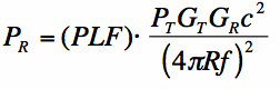
Equation3
Post time: Jan-08-2024


