


As one of the feeding methods of waveguide antennas, the design of microstrip to waveguide plays a crucial role in energy transmission. The traditional microstrip to waveguide model is as follows. A probe carrying a dielectric substrate and fed by a microstrip line is inserted into the gap in the wide wall of the rectangular waveguide. The distance between the probe and the short-circuit wall at the end of the waveguide is about four times the operating wavelength. one part. Under the premise of selecting the dielectric substrate, the reactance of the probe depends on the size of the microstrip line, and the reactance of the short-circuit waveguide depends on the position of the short-circuit wall. These parameters are comprehensively optimized to achieve impedance matching of pure resistors and minimize energy loss transmission.
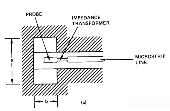
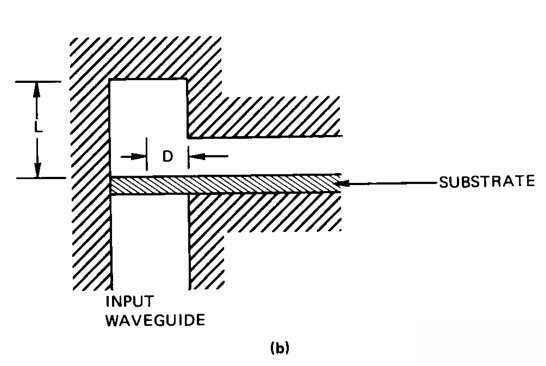
Microstrip to waveguide structure in different views
RFMISO Microstrip Antenna series products:

RM-MA25527-22

RM-MA425435-22
Case
According to the design ideas provided in the literature, design a waveguide to microstrip converter with an operating bandwidth of 40~80GHz. The models from different perspectives are as follows. As a common example, a non-standard waveguide is used. The thickness and dielectric constant of the dielectric material are based on The impedance characteristics of the microstrip probe were adjusted.
Base material: dielectric constant 3.0, thickness 0.127mm
Waveguide size a*b: 3.92mm*1.96mm
The gap size on the wide wall is 1.08*0.268, and the distance from the short-circuit wall is 0.98. See the figure for S parameters and impedance characteristics.

Front view

Rear view
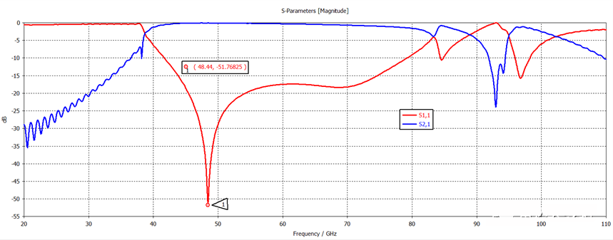
S parameters: 40G-80G
The insertion loss in the passband range is less than 1.5dB.
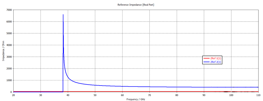
Port impedance characteristics
Zref1: The input impedance of the microstrip line is 50 ohms, Zref1: The wave impedance in the waveguide is about 377.5 ohms;
Parameters that can be optimized: probe insertion depth D, size W*L and the length of the gap from the short-circuit wall. According to the center frequency point 45G, the dielectric constant is 3.0, the equivalent wavelength is 3.949mm, and the one-quarter equivalent wavelength is about 0.96mm. When it is close to pure resistance matching, the waveguide works in the TE10 main mode, as shown in the electric field distribution in the figure below.
E-Field @48.44G_Vector
Post time: Jan-29-2024


