


Microwave coaxial lines carry RF energy between antennas, test instruments, transmitters, receivers, and other microwave components. Their concentric construction provides a controlled transmission path and strong shielding, but performance depends on much more than cable diameter or connector type. Frequency, characteristic impedance, attenuation, power handling, phase stability, bend radius, and the quality of every transition all influence the final result.
This guide explains how microwave coaxial cable works, the main cable constructions, the impedance equation, the causes of RF loss, and the practical checks engineers should make before selecting a coaxial solution.
What Is a Microwave Coaxial Line?
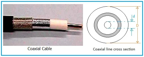
A coaxial transmission line consists of an inner conductor surrounded by a dielectric and a cylindrical outer conductor. Because both conductors share the same axis, the electric field is concentrated mainly within the dielectric while the outer conductor provides the return path and electromagnetic shielding.
The dominant propagation mode is transverse electromagnetic, or TEM. In an ideal coaxial line, TEM propagation has no lower cutoff frequency. Real assemblies still have an upper usable frequency because cable dimensions, dielectric behavior, connector geometry, and higher-order modes limit performance. A cable specified for lower-frequency RF service should therefore not be assumed to perform well at microwave or millimeter-wave frequencies.
Main construction elements
- Inner conductor: carries the forward current and may be solid, stranded, plated, or hollow depending on flexibility, loss, and power requirements.
- Dielectric: maintains spacing and determines much of the impedance, velocity factor, temperature behavior, and dielectric loss.
- Outer conductor: provides the return path and shielding. It may be braided, foil-wrapped, corrugated, or a solid metal tube.
- Protective jacket: protects flexible cable from abrasion, moisture, chemicals, and handling damage.
Common Types of Microwave Coaxial Cable
No single construction is best for every microwave system. The correct choice depends on electrical performance, installation method, movement, environment, and cost.
Flexible coaxial cable
Flexible cable normally uses a stranded or flexible center conductor with braided or foil shielding. It is convenient for laboratory setups, equipment interconnects, and installations that require repeated routing. Its trade-offs can include higher attenuation, lower shielding effectiveness, and greater phase change with bending than rigid constructions.
Semi-rigid coaxial cable
Semi-rigid cable uses a solid outer conductor, commonly formed into a permanent route. It offers excellent shielding, predictable impedance, and good phase stability. It is widely used inside microwave assemblies, but installation requires the correct forming tools and respect for the specified minimum bend radius.
Hand-formable or conformable cable
Hand-formable cable provides a practical middle ground. It can be routed more easily than semi-rigid cable while retaining better shielding and shape stability than many flexible cables. Performance should still be checked after forming because sharp bends and connector stress can change return loss.
Rigid and air-dielectric coaxial line
Rigid coaxial line uses solid conductors and may use air or low-loss dielectric supports. It is suitable for low-loss or higher-power transmission where size and installation complexity are acceptable. Broadcast, radar, and test systems may use rigid sections when flexible cable loss would be excessive.
Double-shielded and phase-stable cable
Additional shielding can reduce leakage and susceptibility to electromagnetic interference. Phase-stable constructions are designed to limit electrical-length changes caused by temperature, flexure, or aging. These characteristics matter in phased arrays, calibration paths, coherent receivers, and vector network analyzer measurements.
Characteristic Impedance of a Coaxial Line
Characteristic impedance is determined by the ratio of the outer conductor's inner diameter to the inner conductor's outer diameter, together with the dielectric's relative permittivity. For a nonmagnetic coaxial line:
Z0 = (60 / √εr) ln(D/d) Ω
or equivalently:
Z0 = (138 / √εr) log10(D/d) Ω
Here, D is the inner diameter of the outer conductor, d is the outer diameter of the inner conductor, and εr is the dielectric's relative permittivity. The two expressions are equivalent because they use different logarithm bases.
Most RF and microwave systems use 50 Ω because it provides a useful balance between power handling and attenuation. A 75 Ω system is common in video, broadcast, and some communications applications. Mixing 50 Ω and 75 Ω components creates an impedance discontinuity that increases reflections and measurement uncertainty.
Why Microwave Coaxial Cable Loses Signal
Insertion loss normally increases with both frequency and cable length. The datasheet value should be checked at the actual operating frequency and converted to the installed length rather than treated as a fixed number.
Conductor loss
At microwave frequencies, skin effect concentrates current near conductor surfaces. Effective resistance rises as frequency increases, so conductor material, plating quality, surface finish, and conductor diameter all influence attenuation.
Dielectric loss
The dielectric absorbs part of the electromagnetic energy. Its loss tangent, temperature, moisture exposure, and operating frequency affect the result. Low-loss dielectric materials are often selected for long runs and precision measurement paths.
Mismatch and connector loss
Cable-to-connector transitions, adapters, damaged interfaces, poor assembly, and incorrect torque can introduce reflections. Return loss or VSWR should be evaluated across the full operating band, including every connector and transition in the signal path.
Bending and installation effects
Tight bends can deform the coaxial geometry and change impedance. Repeated flexure can also alter insertion loss and phase. Follow the cable manufacturer's static and dynamic bend-radius limits and provide strain relief near connectors.
How to Select a Microwave Coaxial Line
Start with the complete installed signal path, not the cable alone. The following checks help prevent avoidable loss, mismatch, overheating, and mechanical failure.
- Confirm the frequency range. Verify the cable, connectors, adapters, and test data all cover the highest operating frequency.
- Match the system impedance. Use the same nominal impedance throughout the path unless a deliberate impedance-transforming network is provided.
- Calculate total insertion loss. Combine the cable loss at the operating frequency with connector, adapter, and transition losses. Include margin for temperature and aging where appropriate.
- Check power handling. Review average power, peak power, VSWR, ambient temperature, altitude, connector rating, and duty cycle. High mismatch can create local voltage or current stress.
- Define phase requirements. For coherent or phase-matched systems, specify phase stability versus temperature and flexure as well as amplitude loss.
- Choose compatible connectors. Connector series have different frequency, power, mating-cycle, and mechanical limits. Avoid unnecessary adapters and verify interface condition before use.
- Review routing and environment. Consider bend radius, movement, vibration, moisture, chemicals, temperature range, shielding, and flame or low-smoke requirements.
- Plan verification. For critical assemblies, measure insertion loss and return loss after installation. Phase-matched systems may also require electrical-length verification.
Coaxial Line or Waveguide?
Coaxial cable is compact, shielded, and easy to route, making it practical for many RF and lower microwave interconnections. As frequency, power, or allowable loss becomes more demanding, waveguide can offer lower transmission loss and higher power capacity, although it is larger and less flexible.
Many systems use both technologies. A properly selected waveguide-to-coaxial adapter transfers energy between the coaxial TEM mode and the required waveguide mode while controlling mismatch. For transition design considerations, see our waveguide-to-coaxial adapter selection guide.
Typical Applications
- Vector network analyzer and spectrum analyzer connections
- Antenna measurement and calibration setups
- Radar, satellite, and wireless communication equipment
- Signal generators, amplifiers, receivers, and frequency converters
- Internal interconnects in microwave modules and test fixtures
- Transitions between coaxial equipment ports and waveguide components
Frequently Asked Questions
Does coaxial cable have a cutoff frequency?
The dominant TEM mode has no theoretical lower cutoff frequency. However, every real cable assembly has a maximum recommended frequency because higher-order modes, connector geometry, loss, and manufacturing tolerances eventually limit usable performance.
Why is 50 Ω common in microwave systems?
Fifty ohms is widely used because it provides a practical compromise between low attenuation and power handling. It is also the standard impedance for most RF test equipment and many microwave components.
Can a longer cable be compensated by using a higher-power source?
Additional source power may restore received level in some systems, but it does not remove cable heating, noise-figure impact, phase variation, mismatch, or power-rating limits. Reducing path loss is usually the more reliable engineering approach.
What should be tested after installation?
At minimum, check insertion loss and return loss across the operating band. Precision systems may also require phase, group delay, time-domain discontinuity, shielding, or passive intermodulation measurements.
For help selecting a waveguide-to-coaxial transition or integrating coaxial and waveguide sections in a microwave system, contact RF MISO with the required frequency band, interface, power level, and mechanical constraints.
Post time: Dec-15-2023


