


Electronic engineers know that antennas send and receive signals in the form of waves of electromagnetic (EM) energy described by Maxwell's equations. As with many topics, these equations, and the propagation, properties of electromagnetism, can be studied at different levels, from relatively qualitative terms to complex equations.
There are many aspects to electromagnetic energy propagation, one of which is polarization, which can have varying degrees of impact or concern in applications and their antenna designs. The basic principles of polarization apply to all electromagnetic radiation, including RF/wireless, optical energy, and are often used in optical applications.
What is antenna polarization?
Before understanding polarization, we must first understand the basic principles of electromagnetic waves. These waves are composed of electric fields (E fields) and magnetic fields (H fields) and move in one direction. The E and H fields are perpendicular to each other and to the direction of plane wave propagation.
Polarization refers to the E-field plane from the perspective of the signal transmitter: for horizontal polarization, the electric field will move sideways in the horizontal plane, while for vertical polarization, the electric field will oscillate up and down in the vertical plane.(figure 1).
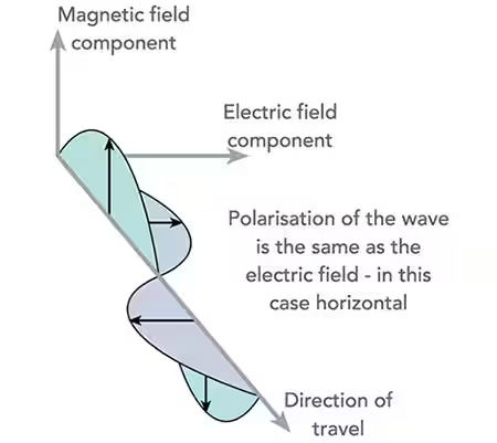
Figure 1: Electromagnetic energy waves consist of mutually perpendicular E and H field components
Linear polarization and circular polarization
Polarization modes include the following:
In basic linear polarization, the two possible polarizations are orthogonal (perpendicular) to each other (Figure 2). In theory, a horizontally polarized receiving antenna will not "see" a signal from a vertically polarized antenna and vice versa, even if both operate at the same frequency. The better they are aligned, the more signal is captured, and energy transfer is maximized when polarizations match.
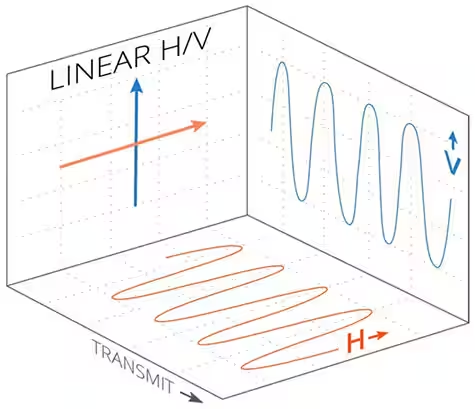
Figure 2: Linear polarization provides two polarization options at right angles to each other
The oblique polarization of the antenna is a type of linear polarization. Like basic horizontal and vertical polarization, this polarization only makes sense in a terrestrial environment. Oblique polarization is at an angle of ±45 degrees to the horizontal reference plane. While this is really just another form of linear polarization, the term "linear" usually only refers to horizontally or vertically polarized antennas.
Despite some losses, signals sent (or received) by a diagonal antenna are feasible with only horizontally or vertically polarized antennas. Obliquely polarized antennas are useful when the polarization of one or both antennas is unknown or changes during use.
Circular polarization (CP) is more complex than linear polarization. In this mode, the polarization represented by the E field vector rotates as the signal propagates. When rotated to the right (looking out from the transmitter), circular polarization is called right-handed circular polarization (RHCP); when rotated to the left, left-handed circular polarization (LHCP) (Figure 3)
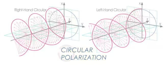
Figure 3: In circular polarization, the E field vector of an electromagnetic wave rotates; this rotation can be right-handed or left-handed
A CP signal consists of two orthogonal waves that are out of phase. Three conditions are required to generate a CP signal. The E field must consist of two orthogonal components; the two components must be 90 degrees out of phase and equal in amplitude. A simple way to generate CP is to use a helical antenna.
Elliptical polarization (EP) is a type of CP. Elliptically polarized waves are the gain produced by two linearly polarized waves, like CP waves. When two mutually perpendicular linearly polarized waves with unequal amplitudes are combined, an elliptically polarized wave is produced.
The polarization mismatch between antennas is described by the polarization loss factor (PLF). This parameter is expressed in decibels (dB) and is a function of the difference in polarization angle between the transmitting and receiving antennas. Theoretically, the PLF can range from 0 dB (no loss) for a perfectly aligned antenna to infinite dB (infinite loss) for a perfectly orthogonal antenna.
In reality, however, the alignment (or misalignment) of polarization is not perfect because the mechanical position of the antenna, user behavior, channel distortion, multipath reflections, and other phenomena can cause some angular distortion of the transmitted electromagnetic field. Initially, there will be 10 - 30 dB or more of signal cross-polarization "leakage" from the orthogonal polarization, which in some cases may be enough to interfere with the recovery of the desired signal.
In contrast, the actual PLF for two aligned antennas with ideal polarization may be 10 dB, 20 dB, or greater, depending on the circumstances, and may hinder signal recovery. In other words, unintended cross-polarization and PLF can work both ways by interfering with the desired signal or reducing the desired signal strength.
Why care about polarization?
Polarization works in two ways: the more aligned two antennas are and have the same polarization, the better the strength of the received signal. Conversely, poor polarization alignment makes it more difficult for receivers, either intended or unsatisfied, to capture enough of the signal of interest. In many cases, the "channel" distorts the transmitted polarization, or one or both antennas are not in a fixed static direction.
The choice of which polarization to use is usually determined by the installation or atmospheric conditions. For example, a horizontally polarized antenna will perform better and maintain its polarization when installed near the ceiling; conversely, a vertically polarized antenna will perform better and maintain its polarization performance when installed near a side wall.
The widely used dipole antenna (plain or folded) is horizontally polarized in its "normal" mounting orientation (Figure 4) and is often rotated 90 degrees to assume vertical polarization when required or to support a preferred polarization mode ( Figure 5).
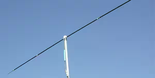
Figure 4: A dipole antenna is usually mounted horizontally on its mast to provide horizontal polarization
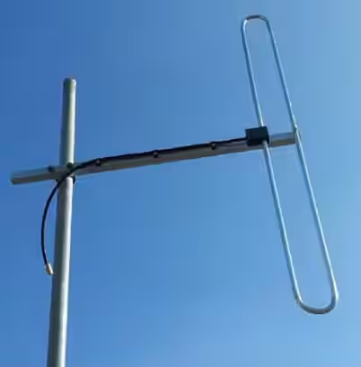
Figure 5: For applications requiring vertical polarization, the dipole antenna can be mounted accordingly where the antenna catches
Vertical polarization is commonly used for handheld mobile radios, such as those used by first responders, because many vertically polarized radio antenna designs also provide an omnidirectional radiation pattern. Therefore, such antennas do not have to be reoriented even if the direction of the radio and antenna changes.
3 - 30 MHz high frequency (HF) frequency antennas are typically constructed as simple long wires strung together horizontally between brackets. Its length is determined by the wavelength (10 - 100 m). This type of antenna is naturally horizontally polarized.
It's worth noting that referring to this band as "high frequency" started decades ago, when 30 MHz was indeed high frequency. Although this description now appears to be outdated, it is an official designation by the International Telecommunications Union and is still widely used.
The preferred polarization may be determined in two ways: either using ground waves for stronger short-range signaling by broadcast equipment using the 300 kHz - 3 MHz medium wave (MW) band, or using sky waves for longer distances through the ionosphere Link. Generally speaking, vertically polarized antennas have better ground wave propagation, while horizontally polarized antennas have better sky wave performance.
Circular polarization is widely used for satellites because the satellite's orientation relative to ground stations and other satellites is constantly changing. Efficiency between transmit and receive antennas is greatest when both are circularly polarized, but linearly polarized antennas can be used with CP antennas, although there is a polarization loss factor.
Polarization is also important for 5G systems. Some 5G multiple-input/multiple-output (MIMO) antenna arrays achieve increased throughput by using polarization to more efficiently utilize the available spectrum. This is achieved using a combination of different signal polarizations and spatial multiplexing of the antennas (space diversity).
The system can transmit two data streams because the data streams are connected by independent orthogonally polarized antennas and can be recovered independently. Even if some cross-polarization exists due to path and channel distortion, reflections, multipath, and other imperfections, the receiver employs sophisticated algorithms to recover each original signal, resulting in low bit error rates (BER) and ultimately improved spectrum Utilization.
in conclusion
Polarization is an important antenna property that is often overlooked. Linear (including horizontal and vertical) polarization, oblique polarization, circular polarization and elliptical polarization are used for different applications. The range of end-to-end RF performance an antenna can achieve depends on its relative orientation and alignment. Standard antennas have different polarizations and are suitable for different parts of the spectrum, providing the preferred polarization for the target application.
Products Recommended:
|
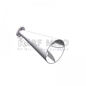
RM-DPHA2030-15 |
||
|
Parameters |
Typical |
Units |
|
Frequency Range |
20-30 |
GHz |
|
Gain |
15 Typ. |
dBi |
|
VSWR |
1.3 Typ. | |
|
Polarization |
Dual Linear |
|
|
Cross Pol. Isolation |
60 Typ. |
dB |
|
Port Isolation |
70 Typ. |
dB |
|
Connector |
SMA-Female |
|
|
Material |
Al |
|
|
Finishing |
Paint |
|
|
Size(L*W*H) |
83.9*39.6*69.4(±5) |
mm |
|
Weight |
0.074 |
kg |
|
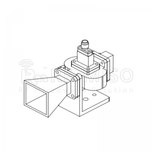
RM-BDHA118-10 |
||
|
Item |
Specification |
Unit |
|
Frequency Range |
1-18 |
GHz |
|
Gain |
10 Typ. |
dBi |
|
VSWR |
1.5 Typ. | |
|
Polarization |
Linear |
|
|
Cross Po. Isolation |
30 Typ. |
dB |
|
Connector |
SMA-Female |
|
|
Finishing |
Paint |
|
|
Material |
Al |
|
|
Size(L*W*H) |
182.4*185.1*116.6(±5) |
mm |
|
Weight |
0.603 |
kg |
|
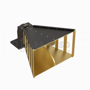
RM-CDPHA218-15 |
||
|
Parameters |
Typical |
Units |
|
Frequency Range |
2-18 |
GHz |
|
Gain |
15 Typ. |
dBi |
|
VSWR |
1.5 Typ. |
|
|
Polarization |
Dual Linear |
|
|
Cross Pol. Isolation |
40 |
dB |
|
Port Isolation |
40 |
dB |
|
Connector |
SMA-F |
|
|
Surface Treatment |
Paint |
|
|
Size (L*W*H) |
276*147*147(±5) |
mm |
|
Weight |
0.945 |
kg |
|
Material |
Al |
|
|
Operating Temperature |
-40-+85 |
°C |
|
RM-BDPHA9395-22 |
||
|
Parameters |
Typical |
Units |
|
Frequency Range |
93-95 |
GHz |
|
Gain |
22 Typ. |
dBi |
|
VSWR |
1.3 Typ. |
|
|
Polarization |
Dual Linear |
|
|
Cross Pol. Isolation |
60 Typ. |
dB |
|
Port Isolation |
67 Typ. |
dB |
|
Connector |
WR10 |
|
|
Material |
Cu |
|
|
Finishing |
Golden |
|
|
Size (L*W*H) |
69.3*19.1*21.2 (±5) |
mm |
|
Weight |
0.015 |
kg |
Post time: Apr-11-2024


