


A passive electronically scanned array, or PESA radar, typically uses a comparatively centralized RF transmit/receive architecture to feed many antenna elements through a distribution network. Electronically controlled phase shifts set the relative phase at the elements, so the combined radiation forms a beam in a commanded direction. The complete aperture does not need to rotate mechanically for every pointing change.
Quick answer: PESA provides electronic beam steering with a comparatively centralized RF architecture. Its real performance depends on more than the acronym. Engineers must verify gain over scan angle, feed-network loss, operating bandwidth, sidelobes, polarization, calibration, duty cycle, thermal limits and the measurement reference plane before deciding whether a design meets the application.
This matters because a specification measured only at boresight can hide the conditions that govern field performance. A high peak gain does not show how the beam changes near the edge of the scan sector. A wide operating-frequency range does not prove that beam pointing remains stable across the band. The following sections explain how a PESA works and which questions reduce integration risk.
How Does a PESA Radar Work
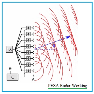
A PESA architecture can be implemented in different ways, but the signal path usually contains five functional stages. Some systems use subarrays or redundant channels, so the block diagram should always be checked against the actual design.
- Waveform generation and RF conversion. The exciter creates the required waveform and converts it to the operating frequency. The transmitter then raises the signal to the required power level.
- Power distribution. A feed network divides the transmitted signal among many paths. The network may use waveguide, transmission lines, power dividers, couplers and other microwave components.
- Phase control. A phase shifter in each element path, or in each subarray path, changes the signal phase according to the commanded beam direction. The phase progression across the aperture determines where constructive interference occurs.
- Radiation and beam formation. The antenna elements radiate together. Their fields add strongly in the selected direction and cancel partially in other directions, creating a main beam and sidelobes.
- Receive operation and calibration. Reflected signals return through the aperture and feed network to the receiver chain. Calibration data correct phase and amplitude differences caused by component tolerances, temperature, frequency and aging.
Electronic steering can move the beam much faster than physically repositioning a large aperture. However, the useful scan rate also depends on waveform timing, control latency, signal processing and the radar resource scheduler. Antenna steering speed alone does not define how many targets or tasks the complete radar can support.
Why Is It Called a Passive Electronically Scanned Array
The word passive describes the RF architecture at the aperture. In a conventional PESA, the antenna elements do not each contain a complete active transmit and receive module. A centralized RF chain supplies and receives energy through the feed network, while the phase-control components shape the beam. The array still needs electrical power for control, switching, cooling and other functions.
PESA radar is also different from passive radar. Passive radar normally detects reflections from external transmitters or other illuminators of opportunity. PESA is an antenna and RF-distribution architecture that can be used in an actively transmitting radar. Confusing these two meanings leads to incorrect system requirements.
Which Parameters Determine PESA Performance
The most useful specification is a matrix of performance over frequency, scan angle, polarization and operating condition. The table below lists the items that should be defined before comparing arrays or requesting a quotation.
| Parameter | Why it matters | What to request |
|---|---|---|
| Operating band and instantaneous bandwidth | Phase and amplitude errors can vary with frequency. | Usable bandwidth and limits at each required waveform condition. |
| Scan sector | Gain, beamwidth, sidelobes and polarization normally change away from boresight. | Patterns at representative frequencies and scan angles, including the edge of coverage. |
| Gain, EIRP and receive sensitivity | System range depends on the complete transmit and receive budgets. | Reference planes, feed losses, duty cycle and receiver assumptions. |
| Sidelobe and cross-polarization levels | These affect interference, clutter response and polarization purity. | Definitions, cuts, frequency points and scan conditions. |
| Element spacing and layout | Spacing influences grating lobes and available scan range. | Geometry, active aperture size and the intended maximum frequency. |
| Power and thermal conditions | A centralized high-power chain and feed components must operate within their limits. | Peak and average power, pulse width, duty cycle, cooling method and temperature range. |
| Calibration and stability | Phase and amplitude drift changes pointing and pattern quality. | Calibration method, update interval, test ports and allowed residual error. |
| Mechanical and RF interfaces | Radomes, connectors, waveguide transitions and mounting can change performance. | Installed configuration, material stack-up, tolerances and reference drawings. |
Why Does Performance Change With Scan Angle
A phased array is usually strongest near boresight, the direction normal to the aperture. As the beam is steered farther away, the projected aperture becomes smaller in the scan direction. The element pattern may also provide less radiation at the commanded angle. Feed errors, mutual coupling, structural tolerances and a radome can add further distortion.
The result can include scan loss, wider beamwidth, shifted sidelobes, higher cross-polarization or pointing error. These changes are not captured by one boresight gain value. For an array intended to scan to a specified angle, request gain and pattern data at boresight, one or more intermediate angles, and the edge of the required sector. Repeat the check at the lowest, center and highest operating frequencies.
Element spacing deserves particular attention. If the spacing is too large relative to wavelength and scan angle, unwanted grating lobes can enter the visible region. A design that is acceptable at the lower end of the band may behave differently at the highest frequency, where the same physical spacing represents more wavelengths.
How Do Bandwidth and Beam Squint Affect a PESA
Many PESA systems use phase shifters to create a phase progression that is correct at a selected frequency. When frequency changes, the same phase setting can point the beam to a different angle. This frequency-dependent pointing shift is commonly called beam squint. The size of the effect depends on bandwidth, scan angle, architecture and the type of phase-control network.
A wideband requirement therefore needs more than a frequency-range statement. Ask for beam pointing, gain, sidelobes and polarization over frequency and scan angle. Some designs use true-time-delay elements, subarray techniques or frequency-dependent corrections to reduce beam squint, but those choices add their own loss, complexity, size and calibration requirements.
Where Do Feed Network Losses Matter
In a typical monostatic PESA using a shared aperture, the feed network participates in both the transmit and receive paths. Power dividers, transmission lines, waveguides, phase shifters, switches and transitions all contribute insertion loss. On transmit, these losses reduce the power delivered to the aperture and generate heat. On receive, loss ahead of the receiver can reduce sensitivity and effective dynamic range.
Loss values must be tied to a clear reference plane. A quoted antenna gain may exclude a cable, rotary joint, waveguide transition, phase-control network or radome that is present in the installed system. During acceptance, compare measured data with the same configuration and reference plane used in the specification.
Does PESA Mean One Frequency or One Target
| Common statement | More accurate interpretation |
|---|---|
| PESA can use only one frequency. | Frequency agility depends on the transmitter, waveform generator, phase-control network, bandwidth and calibration. PESA is not automatically restricted to one fixed frequency. |
| PESA can track only one target. | Target capacity depends on beam scheduling, revisit time, waveform design, receiver channels and processing. A PESA can interleave tasks even though many conventional PESA implementations form one primary transmit beam at a time. |
| PESA is always inexpensive and simple. | It may use fewer distributed active RF modules than an AESA, but the feed network, high-power chain, phase control, calibration, cooling and mechanical integration can still be complex. |
| Electronic steering removes every moving part. | The beam can be steered electronically, but some systems also place the array on a rotating or repositionable platform to extend coverage. |
Eight Questions to Ask Before Integrating a PESA Array
- What operating frequencies and instantaneous bandwidths must be supported, and which values are mandatory across the full scan sector?
- What azimuth and elevation coverage is required, and is the complete aperture mechanically fixed, rotating or otherwise repositioned?
- What gain, EIRP, beamwidth, sidelobe and cross-polarization limits apply at boresight and at the maximum scan angle?
- What peak power, average power, pulse width and duty cycle must the feed network and aperture handle?
- Where are the transmit-power and receive-sensitivity reference planes, and which cable, waveguide, phase-shifter and radome losses are included?
- How will the array be calibrated across frequency, temperature and scan angle, and how will drift be detected after installation?
- What connector, waveguide, mounting, radome, size, weight and environmental constraints apply to the installed configuration?
- Which measurements will prove acceptance, and will the test setup reproduce the operational polarization, frequency, power and scan conditions?
PESA and AESA Serve Different Architecture Choices
PESA and active electronically scanned array radar both use controlled phase relationships to steer beams. Their main difference is where active RF generation and reception occur. A PESA generally routes a centralized transmitter and receiver architecture through a feed network and phase shifters. An AESA distributes many active transmit and receive modules across the aperture or its subarrays. Beamforming implementation—analog, hybrid or digital—is a separate design dimension and should not be treated as synonymous with the PESA/AESA distinction.
AESA can offer greater redundancy, waveform flexibility and rapid multifunction scheduling, but it also creates demanding requirements for power distribution, cooling, calibration and module control. PESA can remain practical when a centralized RF architecture meets the mission and integration requirements. For a detailed architecture comparison, read RF MISO’s AESA vs PESA radar comparison. The correct selection should be based on measurable requirements rather than the assumption that one acronym is always better.
How Should a PESA Array Be Measured and Accepted
Acceptance testing should reproduce the conditions used in the performance specification. At minimum, document the frequency points, polarization, scan commands, power level, duty cycle, calibration state, radome condition and RF reference plane. Measure or verify gain, beamwidth, pointing accuracy, sidelobes and cross-polarization at representative scan angles.
The required range and setup depend on aperture size, frequency and measurement objective. Far-field, compact-range or near-field methods may be appropriate. RF MISO’s antenna testing capabilities describe relevant measurement resources, but the final method and uncertainty budget should be agreed before acceptance testing begins.
RF MISO Support for Array Antenna Evaluation
RF MISO is an RF and microwave antenna manufacturer supporting antenna research, measurement and system integration. RF MISO does not present a complete PESA radar as a standard antenna product. Relevant engineering discussions begin with the antenna aperture, feed and interface requirements that can be verified against a defined frequency band, polarization, gain, beamwidth and mechanical envelope.
Engineers can review RF MISO array antenna products and planar antennas as starting points for component and aperture discussions. Available standard products do not automatically constitute a PESA radar, and suitability must be confirmed against the complete system architecture.
For an initial technical discussion, provide the operating band, instantaneous bandwidth, polarization, required gain, scan sector, sidelobe target, peak and average power, RF interface, aperture size, mounting constraints, environmental conditions and acceptance-test expectations. This information allows the engineering team to identify which antenna and test options require further evaluation.
Send the project requirements to info@rf-miso.com or contact RF MISO through the website.
Frequently Asked Questions
What does PESA stand for
PESA stands for passive electronically scanned array. It typically uses a comparatively centralized RF transmit/receive architecture, a feed network and controlled phase shifts to steer the beam across an antenna aperture.
Why is a PESA called passive if it transmits power
Passive describes the absence of a complete active transmit and receive module at every antenna element. The radar still uses powered RF, control, calibration and cooling hardware.
Can a PESA radar track multiple targets
It can, depending on beam scheduling, revisit time, waveform design, receiver channels and processing. The label PESA alone does not define target capacity.
Is PESA the same as a phased array antenna
PESA is one phased-array RF architecture, while phased array is the broader antenna concept. AESA is another RF architecture. Analog, hybrid and digital beamforming describe how beamforming is implemented and form a separate classification dimension rather than equivalent alternatives to PESA or AESA.
What data should be checked at the maximum scan angle
Check gain or scan loss, beamwidth, pointing accuracy, sidelobes, cross-polarization and impedance behavior at the required frequencies and installed configuration.
When can PESA be a practical choice
PESA can be practical when electronic steering is required and a centralized RF chain can meet the bandwidth, scan, power, reliability, thermal and maintenance requirements. The decision should follow system measurements and lifecycle constraints.
Post time: Oct-28-2026


