


A waveguide-to-coaxial adapter connects a rectangular waveguide interface to a coaxial RF interface while preserving signal integrity across a specified frequency band. It is commonly used when a system must connect waveguide-fed antennas, test equipment, radar modules, transmitters, receivers or other microwave components to coaxial cables and connectors.
The adapter is sometimes called a waveguide converter, coaxial-to-waveguide adapter or waveguide transition. In most passive designs, the transition is reciprocal, so the same component can transfer energy from coaxial line to waveguide or from waveguide to coaxial line. The correct choice depends on frequency band, waveguide size, flange, connector, layout, power and electrical performance.
What Is a Waveguide-to-Coaxial Adapter?
A coaxial cable normally supports a transverse electromagnetic mode, while a rectangular waveguide usually operates in a dominant waveguide mode such as TE10. These two transmission structures have different field distributions and impedances. A waveguide-to-coaxial adapter provides a controlled transition between them.
The waveguide side includes a defined waveguide aperture and flange. The coaxial side includes an RF connector and center conductor. Inside the transition, a probe or coupling structure extends into the waveguide at a carefully selected position. Its geometry, penetration depth and distance from the backshort are optimized to couple energy efficiently and reduce reflections.
Because the transition is frequency sensitive, an adapter should never be selected by connector type alone. The operating band and waveguide designation must be checked first.
How Does a Waveguide-to-Coaxial Adapter Work?
When a signal enters through the coaxial connector, current on the center conductor excites the coupling probe inside the waveguide. The probe launches the required electromagnetic field pattern, and the backshort helps establish the correct phase relationship for efficient power transfer. In the reverse direction, the waveguide field induces a signal in the probe and transfers it to the coaxial line.
Good performance requires the electric field, probe position and waveguide dimensions to be matched over the intended frequency range. If the adapter is used outside its specified band, or if the flange and connector interfaces are not properly assembled, return loss can deteriorate and insertion loss can increase.
Main Types of Waveguide-to-Coaxial Adapters
End-Launch Waveguide-to-Coaxial Adapter
An end-launch waveguide-to-coaxial adapter places the coaxial connector along the waveguide axis or at the end of the assembly. This arrangement can be useful when the system layout has enough axial clearance and a straight cable path is preferred.
Typical advantages include compact routing in line with the component chain, convenient integration with test fixtures and fewer sharp cable bends. The final choice still depends on the mechanical envelope and connector access.
Right-Angle Waveguide-to-Coaxial Adapter
A right-angle waveguide-to-coaxial adapter positions the connector at 90 degrees to the waveguide axis. It is often selected when rack depth, antenna mounting or nearby hardware makes an end-launch connection difficult.
Right-angle construction can simplify cable routing and reduce strain on the connector, but sufficient space must be reserved for the cable bend radius and connector tightening tool.
How to Select the Right Waveguide Adapter
Use the following checklist before ordering or integrating a waveguide-to-coaxial adapter.
1. Confirm the complete operating frequency range
Start with the lowest and highest frequencies used by the system, including test margin. Select an adapter whose specified band covers the entire range. A model that only overlaps part of the required band may show acceptable results at one frequency but poor matching near the band edges.
2. Match the waveguide designation
Verify the waveguide size, such as WR187, WR90, WR62, WR51 or WR28. Similar-looking flanges do not guarantee compatible internal dimensions. The waveguide designation must match the mating component and operating band.
3. Check the flange standard and orientation
Confirm the flange type, hole pattern, alignment, sealing requirement and any requested groove or gasket. Also check whether the installation requires a specific E-plane or H-plane connector orientation. Mechanical mismatch or poor flange contact can create discontinuities and leakage.
4. Select the correct coaxial connector
Choose the connector according to frequency, power, cable type and mating interface. SMA and Type N are common examples, but the correct option depends on the application. Connector gender should also be confirmed before production.
5. Review VSWR, return loss and insertion loss
VSWR and return loss describe impedance matching, while insertion loss describes power lost through the transition. Compare values across the full operating band rather than at a single center frequency. For measurement systems, stable broadband performance is often more important than one best-case point.
6. Confirm power and environmental requirements
Transmit systems may require additional attention to connector power capability, heat dissipation, pressurization and breakdown margin. For outdoor, airborne or industrial use, review temperature range, humidity, vibration, corrosion protection and sealing requirements.
7. Check available installation space
Compare end-launch and right-angle layouts, including cable bend radius and access for tightening. A mechanically convenient adapter reduces stress on the coaxial connector and helps maintain repeatable performance during installation and maintenance.
Common Causes of High VSWR or Excessive Loss
If an installed adapter underperforms, check the complete RF path before replacing the component. Common causes include:
- Using an adapter outside its specified frequency range.
- Selecting the wrong waveguide size or an incompatible flange.
- Loose, damaged or contaminated coaxial connectors.
- Misaligned waveguide flanges, uneven fastener torque or a visible interface gap.
- Using an incorrect gasket or allowing a gasket to obstruct the waveguide aperture.
- Cable damage, excessive bending or calibration reference-plane errors.
- Moisture, dust or foreign material inside the waveguide.
For troubleshooting, inspect and clean both interfaces, verify the model and band, reconnect with the specified torque and measure the adapter with an appropriate vector network analyzer setup. Testing a known-good cable or adapter can help isolate the source of the mismatch.
Typical Applications
Waveguide-to-coaxial adapters are used wherever waveguide components must connect to coaxial equipment or cabling. Typical applications include:
- Antenna measurement and microwave test systems.
- Radar transmit and receive chains.
- Satellite communication and ground-station equipment.
- Point-to-point microwave communication links.
- Laboratory signal generators, analyzers and network analyzers.
- Waveguide-fed horn antennas and other microwave antenna assemblies.
- Research, calibration and system integration fixtures.
RF MISO Waveguide-to-Coaxial Adapter Options
RF MISO supplies waveguide-to-coaxial adapters for multiple standard waveguide bands, with end-launch and right-angle configurations available for different installation requirements. The product examples below cover several commonly used bands from 3.95 GHz to 40 GHz.
For a reliable quotation, provide the required frequency range, waveguide designation, flange type, connector type and gender, orientation, power level, quantity and environmental requirements. A dimensional drawing or system interface sketch is especially helpful when space is limited.
Frequently Asked Questions
Is a waveguide-to-coaxial adapter directional?
A passive adapter is generally reciprocal and can transfer energy in either direction. The names waveguide-to-coaxial and coaxial-to-waveguide usually describe the connected interfaces rather than a one-way signal path.
Can one adapter cover two different waveguide bands?
Normally, one adapter is designed for a specific waveguide size and operating band. If a system uses different waveguide bands, separate adapters or an additional waveguide transition may be required.
What information is required to select an adapter?
At minimum, specify frequency range, waveguide size, flange, coaxial connector and connector gender. Power, VSWR, insertion loss, layout and environmental requirements should also be included when relevant.
Why does adapter performance change after installation?
Flange alignment, fastener torque, connector condition, cable routing, contamination and measurement calibration can all affect the installed result. Verify these items before concluding that the adapter itself is defective.
Can RF MISO support a custom interface?
Custom frequency bands, flange options, connector types and mechanical configurations can be evaluated according to project requirements. Contact RF MISO with the full interface and performance specifications for an engineering review.
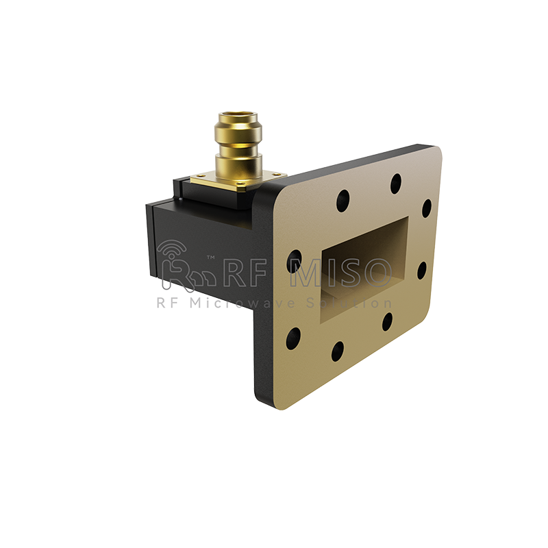
RM-WCA187,3.95-5.85 GHz
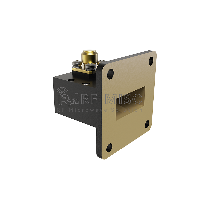
RM-WCA90, 8.2-12.4 GHz
RM-WCA62,12.4-18 GHz
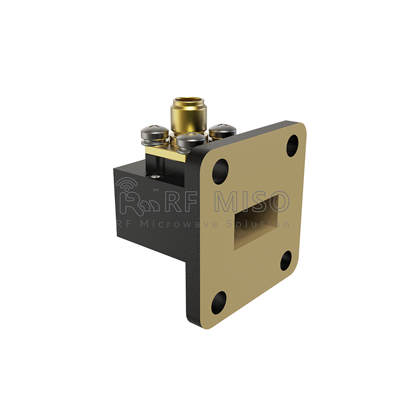
RM-WCA51,15-22 GHz
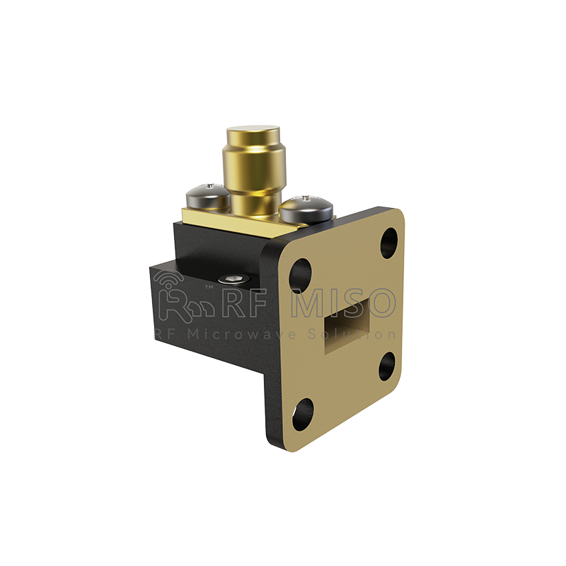
RM-WCA28,26.5-40 GHz
Post time: Dec-18-2023


