


A biconical antenna is a broadband antenna formed by two conductive cones positioned tip to tip and fed at their apexes. Its gradually changing geometry provides a wider operating bandwidth than a conventional thin-wire dipole, making it useful for wideband measurement, electromagnetic compatibility testing, spectrum monitoring, communication and radar applications.
What Is a Biconical Antenna?
A biconical antenna can be viewed as a three-dimensional broadband dipole. The two opposed cones act as radiating elements, while the feed is located at the narrow gap between their tips. Cone angle, cone length, feed geometry and the surrounding structure determine the usable frequency range, impedance match and radiation characteristics.
Depending on its dimensions and installation, the antenna can provide linear polarization and a generally omnidirectional azimuth pattern. Performance changes across the operating band, so the specified gain, VSWR and radiation pattern should always be checked for the intended frequency range.
How Does a Biconical Antenna Work?
RF current enters the antenna at the feed point and travels along the expanding conductive surfaces. Because the conductor widens gradually, the transition from the feed region to free space is smoother over a broad range of frequencies. This geometry helps maintain a usable input impedance and stable radiation over a wider bandwidth than a narrowband dipole.
The antenna does not rely on multipath reflections inside the cones. Radiation is produced by time-varying currents on the conductive surfaces. At higher frequencies, electrical size and feed details can create additional pattern variation, which is why broadband designs must be evaluated across the complete operating band.
Main Design Parameters
- Frequency range: The complete band over which impedance and radiation requirements are met.
- VSWR and impedance: These indicate how efficiently RF power is transferred between the feed line and antenna.
- Gain: Broadband biconical antennas usually provide moderate gain that varies with frequency.
- Radiation pattern: Pattern stability and azimuth coverage should be checked across the band.
- Polarization: Orientation determines the direction of linear polarization.
- Connector and power handling: Both must match the test system or RF source.
- Mechanical size: Cone dimensions affect the lowest usable frequency and installation requirements.
Common Applications
- EMC radiated-emission and immunity measurements
- Wideband antenna and RF system testing
- Spectrum monitoring and signal collection
- Wireless communication and radar experiments
- Laboratory calibration and field measurement systems
Advantages and Limitations
Biconical antennas offer broad bandwidth, relatively simple construction and useful pattern coverage. They can reduce the need to change antennas when a test spans a wide frequency range. Their limitations include moderate gain, physical size at lower frequencies and radiation-pattern variation toward the upper end of the band.
How to Select a Biconical Antenna
Start with the required frequency range, then compare VSWR, gain, polarization, pattern stability, connector type, power handling and mechanical dimensions. The test distance, mounting orientation and surrounding environment should also be considered because nearby structures can affect broadband measurements.
Explore RF MISO's biconical antenna solutions, including the RM-BCA812-2 for 8-12 GHz and the RM-BCA2428-4 for 24-28 GHz. For a model matched to your frequency range and test setup, contact RF MISO.
Biconical Antenna Series Product Introduction
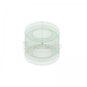
RM-BCA812-2,8-12 GHz
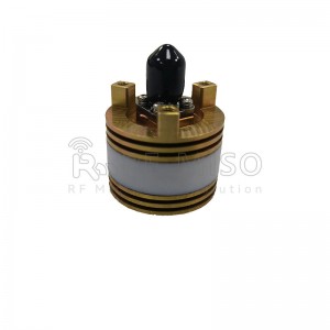
RM-BCA2428-4,24-28 GHz
E-mail:info@rf-miso.com
Phone:0086-028-82695327
Website:www.rf-miso.com
Post time: Oct-19-2023


