


Right-hand circular polarization (RHCP) and left-hand circular polarization (LHCP) describe the direction in which the electric-field vector rotates as an electromagnetic wave propagates. Correct identification matters in satellite links, radar, antenna measurement and other RF systems because the transmitting and receiving antennas must use compatible polarization to achieve efficient power transfer.
This guide explains the viewing convention, the practical hand rule, the field-component relationship, axial ratio and the main specifications to check when selecting a circularly polarized antenna.
RF MISO Circularly Polarized Horn Antenna Examples
RF MISO supplies circularly polarized horn antenna models for selected operating bands. The examples below illustrate different frequency-range options; always confirm handedness, axial ratio, gain, interface and mechanical data in the current model datasheet before selection.

RM-CPHA82124-20 | 8.2–12.4 GHz circularly polarized horn antenna

RM-CPHA1840-12 | 18–40 GHz circularly polarized horn antenna

RM-CPHA218-16 | 2–18 GHz circularly polarized horn antenna
Explore the complete category: RF MISO circular polarization horn antennas, including RHCP, LHCP and dual-circular-polarization options by model.
What Is Circular Polarization?
Polarization describes the path traced by the electric-field vector at a fixed point in space. In linear polarization, the vector remains on a straight line. In ideal circular polarization, its magnitude is constant while the vector rotates through 360 degrees during each RF cycle. Practical antennas usually produce a slightly elliptical path, so circularity is evaluated by axial ratio. An ideal circularly polarized wave has a 0 dB axial ratio; a lower measured axial ratio indicates polarization closer to a circle.
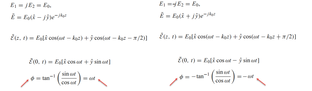
Circular polarization can be formed by two orthogonal linear field components with equal amplitude and a phase difference of plus or minus 90 degrees. The sign of that quadrature phase relationship determines whether the wave is RHCP or LHCP under the stated convention.
RHCP vs LHCP: State the Viewing Convention
Handedness can appear reversed when the same rotating field is viewed from opposite directions. To avoid ambiguity, always state the observation direction. Under the commonly used IEEE convention, handedness is defined while looking in the direction of wave propagation, from the source toward the direction of travel.
A practical method is to point your thumb in the propagation direction. If the electric-field rotation follows the curl of the fingers on your right hand, the wave is RHCP under this convention; if it follows the left-hand curl, it is LHCP. Because some documents and disciplines use a different viewing perspective, confirm the convention in the antenna datasheet and test procedure before comparing results.

Field Components and Phase Relationship
Consider two plane-wave components traveling along the z-axis. One electric-field component is oriented along x with amplitude Ex; the second is oriented along y with amplitude Ey. Their vector sum determines the resulting polarization state.
When only one component is present, the wave is linearly polarized along that axis. When both components are present, their relative amplitude and phase determine whether the result is linear, circular or elliptical polarization.
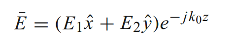
The field relationship can be summarized as follows:
- If Ex is nonzero and Ey is zero, polarization is linear along x.
- If Ey is nonzero and Ex is zero, polarization is linear along y.
- If both components are in phase, their vector sum remains linear at a fixed angle.
- If the components have equal amplitude and a phase difference of plus or minus 90 degrees, the result is ideal circular polarization.
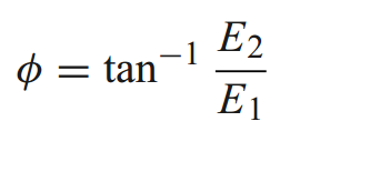
If the orthogonal components are unequal, or the phase difference is not exactly 90 degrees, the field traces an ellipse rather than a circle. This is why an antenna datasheet should specify axial ratio over frequency and, where relevant, over the intended angular coverage. Handedness alone does not describe polarization quality.
Why Polarization Matching Matters
A receiving antenna extracts the greatest available power when its polarization is matched to the incoming wave. Opposite ideal circular polarization states are orthogonal, so an RHCP/LHCP mismatch can produce substantial polarization loss. Real antennas provide finite cross-polarization rejection, and measured performance also depends on axial ratio, alignment, reflections and the surrounding test environment.
Reflections from conducting surfaces can change the apparent polarization state, and radomes, fixtures or nearby structures may distort the field. For reliable verification, align both antennas on boresight, use a known polarization reference, compare received power for RHCP and LHCP configurations, and measure axial ratio and cross-polarization performance across the required band.
How to Select an RHCP or LHCP Antenna
Before choosing a circularly polarized horn antenna, define the complete operating requirement rather than selecting by frequency alone:
- Frequency range: confirm full-band coverage, not only the center frequency.
- Polarization: specify RHCP, LHCP or dual circular polarization and the handedness convention.
- Axial ratio: check the required limit across frequency and angular coverage.
- Gain and beamwidth: match link budget, coverage and measurement-distance needs.
- Impedance match: review VSWR or return loss over the complete band.
- RF interface and power: verify connector or waveguide interface and power-handling needs.
- Mechanical integration: confirm envelope, mounting interface, orientation and environmental requirements.
Talk to an RF MISO Antenna Specialist
RF MISO is an RF and microwave antenna manufacturer and supplier. Share your frequency range, required handedness, gain, axial ratio, interface and installation constraints so our team can help identify a suitable standard model or discuss the application requirements.
Post time: May-21-2024


